


3
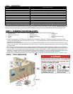
TABLE 2 – CIRCUIT WORKSHEET
Circuit Amperage Appliance(s) or Circuits
A4 15A
B4 15A
A5 20A
B5 20A
A6 20A
B6 20A
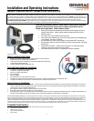
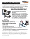
STEP 2: INSTALLATION PROCEDURE:
PLEASE READ THIS MANUAL IN ITS ENTIRETY BEFORE ATTEMPTING TO UNPACK, ASSEMBLE, INSTALL, OPERATE OR MAINTAIN THIS EQUIPMENT.
HAZARDOUS VOLTAGES ARE PRESENT INSIDE TRANSFER SWITCH ENCLOSURES THAT CAN CAUSE DEATH OR SEVERE PERSONAL INJURY. FOLLOW PROPER INSTALLATION,
OPERATION AND MAINTENANCE PROCEDURES TO AVOID HAZARDOUS VOLTAGES. TURN OFF THE MAIN CIRCUIT BREAKER IN THE LOAD CENTER BEFORE STARTING
INSTALLATION.
I. TRANSFER SWITCH INSTALLATION:
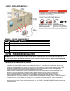
1. Select a location on the left or right side of the load center to mount transfer switch, as it is provided with a 24” flexible conduit wiring harness. Remove the
front cover of the load center, save the screws. Locate and remove a knockout (KO) on the lower side of the load center that matches the conduit fitting size on
the wiring harness.
2. Determine if the wiring harness needs to be shortened. If so, remove the wires from the wiring harness and cut conduit to desired length. [NOTE: The
Electrical Non-Metallic Tubing (ENT) provided is UL Listed and recognized by the National Electrical Code (NEC). However, some local codes and inspectors
may prohibit its use in buildings that exceed (3) floors above grade.]
3. Attach the wiring harness to the load center; hold the transfer switch in position against the wall on which it is to be mounted and using the provided template,
mark the holes on the wall for the anchoring screws and anchor transfer switch to wall (anchors not provided).
4. Remove transfer switch cover, save screws, allow the cover to hang down, supported by the wattmeter wires.
5. Install appropriately sized conduit, fittings and wire between the Power Inlet Box (PIB) mounted on the building exterior and the transfer switch, referring to
section III – Power Inlet Box installation instructions below. Locate and remove a KO in the transfer switch, pull wire into transfer switch enclosure and secure
wire with fitting.
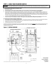
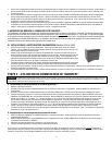
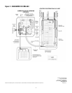
6. Using provided wire connector, connect the generator green ground wire with the green wire inside the transfer switch. Connect the generator white neutral
wire into neutral bar on the left. Using provided wire connectors, connect the generator black wire to black wiring going to Meter “A”. Repeat for generator red
wire to Meter “B”. See FIGURE 2 WIRING DIAGRAM. Reinstall transfer switch cover.
7. In the main load center, remove the wires from the breakers for the loads that will be relocated to the transfer switch. Cut each blue harness wire (A4-B6) to a
convenient length, strip off 5/8” insulation and connect to the wires removed from the breakers per TABLE 2 with the provided wire connectors.
8. Remove two adjacent single pole breakers from which the load wires were removed and install the NEW 60A 2-pole circuit breaker (as required in the Other
Items Needed section) in their place. Insert the unmarked BLACK wires from the harness into the new circuit breaker. Terminate the WHITE and GREEN wire in
the harness in an open position in the Neutral and Ground bars respectively. If there is no separate ground bar, insert the GREEN wire into an open position in
the NEUTRAL bar, and tighten.
9. Reinstall the main load center dead front cover, and turn ON the MAIN breaker in the main load center. Turn ON all branch circuit breakers in both panels. Turn
ON the UTIL MAIN in the transfer switch. Check that power is restored to all appliances. Installation is now complete.
II. EXPANDING OR RECONFIGURING YOUR TRANSFER SWITCH:
This transfer switch ships from the factory with certain popular branch circuit breaker sizes. However, the circuit breaker assortment can be modified to
suit specific requirements, and this does not void the UL Listing. For example, if the 2-pole 20 amp circuit breaker is not needed, it may be removed from
the panel and replaced with any combination of the following: two separate full size breakers, four tandem (half size) breakers, one full size and two
tandems, or a quad breaker. If additional circuit(s) are added, the installer is responsible for providing appropriately sized wire(s) for each circuit.
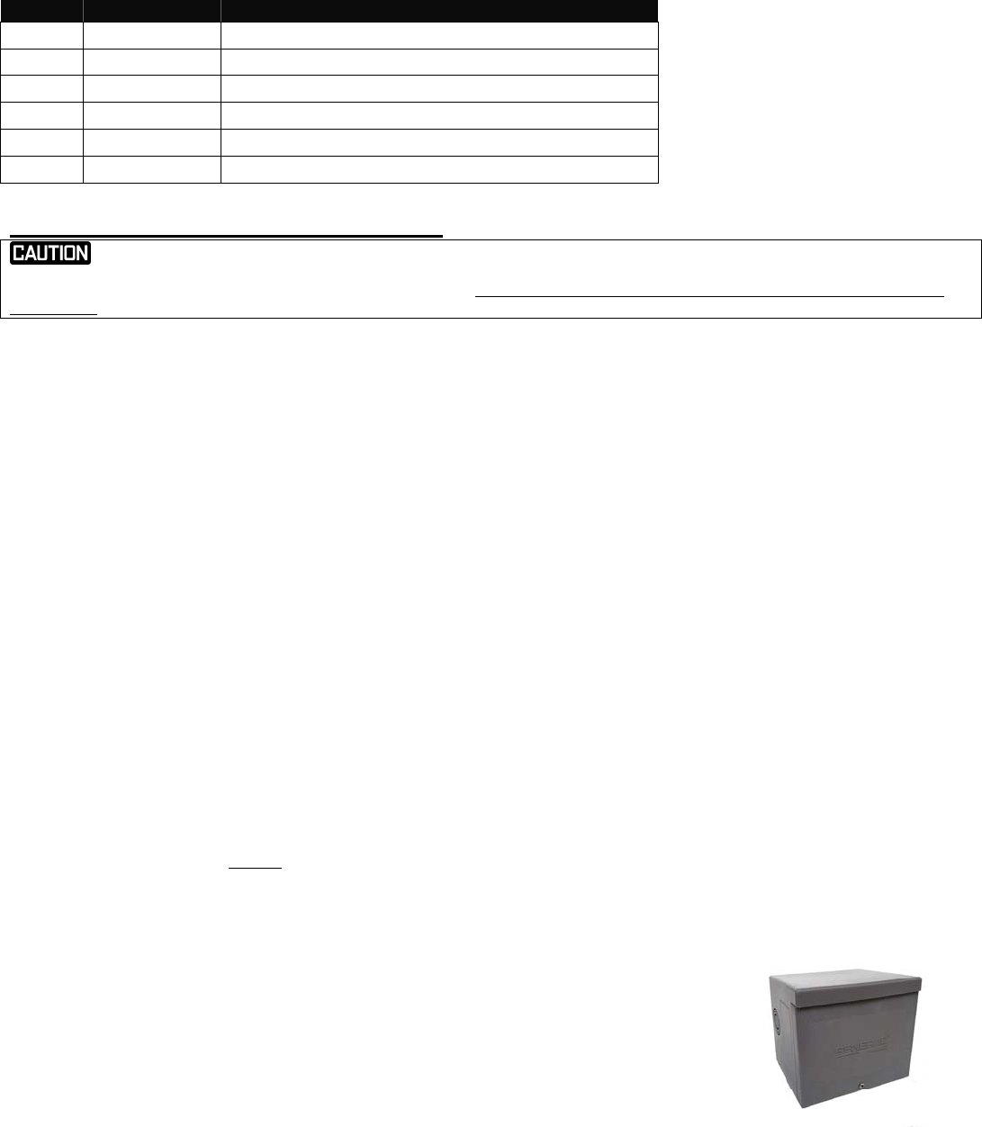
III. INSTALLING THE POWER INLET BOX (Models 6294 and 6408 Only)
1. Remove the front cover of the Power inlet box. Remove the 3 screws that secure the flanged inlet to the bottom
plate. For installations where side clearance exceeds 12” on both sides, remove the 4 screws that secure the
bottom plate to the box.
2. Mount the power inlet box on the outside of the building in a convenient location (minimum 24” above grade), using
the four holes provided in the back of the enclosure. Use sealant around the anchoring screws to keep water from
entering the box at these mounting holes.
Using approved wiring methods, install the wiring through one of the
knockouts provided in the enclosure. Be sure to seal around the hole in the building where the conduit enters
through the wall.
3. Extend wiring inside the power inlet box approx. 8” from the point of entrance. Attach green or bare ground wire to
green lead provided in power inlet box with wire nut (provided by installer). Strip and insert incoming leads into
terminals on flanged inlet. Insert white wire (neutral) into nickel-plated screw terminal or white marking on the flanged inlet.
4. Carefully fold wires into the enclosure and reattach the bottom assembly or inlet onto box with screws removed earlier. Installation is complete.