


Generac
®
Power Systems, Inc. 3
2.1 INTRODUCTION TO INSTALLATION
This equipment has been wired and tested at the fac-
tory. Installing the switch includes the following pro-
cedures:
• Mounting the enclosure.
• Connecting utility and generator power source leads.
• Connecting the load leads.
• Connecting the generator sensing leads.
• Connecting any auxiliary contact (if needed)
• Installing/connecting any options and accessories.
• Testing functions.
2.2 UNPACKING
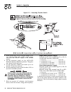
Carefully unpack the transfer switch. Inspect closely
for any damage that might have occurred during ship-
ment. The purchaser must file with the carrier any
claims for loss or damage incurred while in transit.
Check that all packing material is completely
removed from the switch prior to installation.
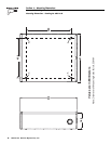
2.3 MOUNTING
Mounting dimensions for the transfer switch enclo-
sure are in this manual. Enclosures are typically
wall-mounted. See “Mounting Dimensions” on page 8.
Handle transfer switches carefully when
installing. Do not drop the switch. Protect the
switch against impact at all times, and against
construction grit and metal chips. Never install
a transfer switch that has been damaged.
Install the transfer switch as close as possible to the
electrical loads that are to be connected to it. Mount
the switch vertically to a rigid supporting structure.
To prevent switch distortion, level all mounting
points. If necessary, use washers behind mounting
holes to level the unit.
2.4 CONNECTING POWER SOURCE
AND LOAD LINES
Make sure to turn OFF both the UTILITY
(Normal) and EMERGENCY (Standby genera-
tor) power supplies before trying to connect
power source and load lines to the transfer
switch. Supply voltages are extremely high
and dangerous. Contact with such high volt-
age power supply lines causes extremely haz-
ardous, possibly lethal, electrical shock.
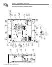
Wiring diagrams and electrical schematics are pro-
vided in this manual. Power source and load connec-
tions are made at a transfer mechanism, inside the
switch enclosure.
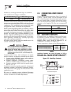
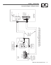
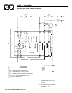
2.4.1 2-POLE MECHANISM
These switches (Figure 2.1) are used with a single
phase system, when the single phase NEUTRAL line
is to be connected to a Neutral Lug and is not to be
switched.
Figure 2.1 — Typical 2-Pole Transfer Mechanism
(200 Amp Shown)
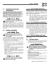
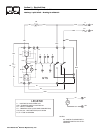
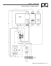
2.4.2 3-POLE MECHANISM
These switches (Figure 2.2) are used with a three
phase system, when the three phase NEUTRAL line is
to be connected to a NEUTRAL lug and is not to be
switched. It is also used with a single phase system
when the neutral is to be switched (NEUTRAL to be
connected to third pole).
Figure 2.2 — Typical 3-Pole Transfer Mechanism
(200 Amp Shown)
◆
DANGER
!
Section 2 — Installation
Generac GTS “W” Type Transfer Switch