


4 Generac
®
Power Systems, Inc.
Solderless, screw-type terminal lugs are standard.
The conductor size range is as follows:
Conductor sizes must be adequate to handle the max-
imum current to which they will be subjected; based
on the 75°C column of tables, charts, etc. used to size
conductors. The installation must comply fully with
all applicable codes, standards and regulations.
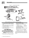
Before connecting wiring cables to terminals, remove
any surface oxides from the cable ends with a wire
brush. All power cables should enter the switch next
to transfer mechanism terminals. If ALUMINUM con-
ductors are used, apply corrosion inhibitor to con-
ductors. Tighten terminal lugs to the torque values as
noted on the decal located on the inside of the door.
After tightening terminal lugs, carefully wipe away
any excess corrosion inhibitor.
All power cables should enter the switch next to the
transfer mechanism terminals.
Use a torque wrench to tighten the conduc-
tors, being sure not to overtighten, or dam-
age to the switch base could occur. If under-
tightened, a loose connection would result,
causing excess heat which could damage the
switch base.
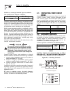
Connect power source load conductors to clearly
marked transfer mechanism terminal lugs as follows
1. Connect utility (NORMAL) power source cables to
switch terminals N1, N2, (N3).
2. Connect emergency (STANDBY) source power
cables to transfer switch terminals E1, E2, (E3).
3. Connect customer LOAD leads to switch termi-
nals T1, T2, T3.
Conductors must be properly supported, of approved
insulative qualities, protected by approved conduit,
and of the correct wire gauge size in accordance with
applicable codes.
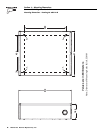
Be sure to maintain proper electrical clearance
between live metal parts and grounded metal. Allow
at least 1/2 inch for 100-400 amp circuits.
2.5 CONNECTING START CIRCUIT
WIRES
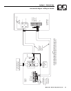
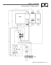
Control system interconnections (Page 11) consist of
UTILITY 1 and 2, LOAD 1 and 2; and leads 23 and
194. Control system interconnection leads must be
run in a conduit that is separate from the AC power
lead. Recommended wire gauge sizes for this wiring
depends on the length of the wire, as recommended
below:
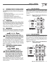
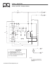
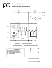
2.6 AUXILIARY CONTACTS
If desired, there are Auxiliary Contacts on the trans-
fer switch to operate customer accessories, remote
advisory lights, or remote annunciator devices. A
suitable power source must be connected to the
COMMON (C) terminal. See Figure 2.3.
Contact operation is shown in the following chart:
NOTE:
Auxiliary Contacts are rated 10 amps at 125 or
250 volts AC. DO NOT EXCEED THE RATED
VOLTAGE AND CURRENT OF THE CONTACTS.
Figure 2.3 – Auxiliary Contacts
Optional
Auxiliary Contact
(Actuated)
Side views shown in Utility position
!
Section 2 — Installation
Generac GTS “W” Type Transfer Switch
MAXIMUM WIRE LENGTH RECOMMENDED WIRE
SIZE
460 feet (140m) No. 18 AWG.
461 to 730 feet (223m) No. 16 AWG.
731 to 1,160 feet (354m) No. 14 AWG.
1,161 to 1,850 feet (565m) No. 12 AWG.
Switch Position
Utility Standby
Common to Normally Open Open Closed
Common to Normally Closed Closed Open
Switch Rating Wire Range
200A #4-400 MCM