


2
Section 1 — General Information
ATS “HS” Type Transfer Switch
1.1 INTRODUCTION
This manual has been prepared especially for the
purpose of familiarizing personnel with the design,
application, installation, operation and servicing of
the applicable equipment. Read the manual carefully
and comply with all instructions. This will help to
prevent accidents or damage to equipment that might
otherwise be caused by carelessness, incorrect appli-
cation, or improper procedures.
Every effort has been expended to make sure that the
contents of this manual are both accurate and cur-
rent. The manufacturer, however, reserves the right
to change, alter or otherwise improve the product at
any time without prior notice.
1.2 EQUIPMENT DESCRIPTION
The automatic transfer switch is used for transfer-
ring electrical load from a UTILITY (NORMAL) power
source to an EMERGENCY (STANDBY) power source.
Such a transfer of electrical loads occurs automati-
cally when the UTILITY power source has failed or is
substantially reduced and the EMERGENCY source
voltage and frequency have reached an acceptable
level. The transfer switch prevents electrical feedback
between two different power sources (such as the
UTILITY and EMERGENCY sources) and, for that
reason, codes require it in all standby electric system
installations.
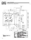
The transfer switch consists of a transfer mecha-
nism, service disconnect circuit breaker, a relay
control, fuses, and a terminal strip for connection of
sensing wires.
This transfer switch is suitable for use as service
entrance equipment.
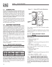
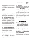
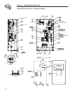
1.2.1 TRANSFER SWITCH MECHANISM
These switches (Figure 1.1) are used with a single-
phase system, when the single-phase NEUTRAL line
is to be connected to a Neutral Lug and is not to be
switched.
Solderless, screw-type terminal lugs are standard.
Switch Wire Conductor Tightening
Rating Range Torque
100A #14-1/0 AWG 50 in-lbs.
200A #6-250 MCM 275 in-lbs.
This transfer switch is suitable for control of motors,
electric discharge lamps, tungsten filament and elec-
tric heating equipment where the sum of motor full
load ampere ratings and the ampere ratings of other
loads do not exceed the ampere rating of the switch
and the tungsten load does not exceed 30 percent of
the switch rating.
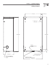
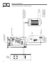
Figure 1.1 — Typical ATS Transfer Mechanism
UTILITY
CLOSING
COIL
GENERATOR
CLOSING
COIL
UTILITY LUGS
GENERATOR
LUGS (E1 & E2)
LOAD LUGS (T1 & T2)
This transfer switch is for use in optional standby
systems only.
This transfer switch is suitable for use on a circuit
capable of 10,000 rms symmetrical amperes, 240
VAC maximum.
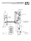
1.2.2 SERVICE DISCONNECT CIRCUIT
BREAKER
The service disconnect circuit breaker for the 100
amp models are:
• Siemens, Type BQ, 2-pole
• 120/240VAC, 100A
• 50/60 Hertz
• Heating, Air Conditioning and Refrigeration (HACR)
rated
• Wire range: #1 - #8 AWG.
• The conductor tightening torque is 50 in-lbs.
The service disconnect circuit breaker for the 200
amp models are:
• Siemens, Type QN, 2-pole
• 120/240VAC, 200A
• 50/60 Hertz
• Heating, Air Conditioning and Refrigeration (HACR)
rated
• Wire range: 300 KCMIL - 4 AWG
• The conductor tightening torque is 250 in-lbs.
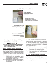
1.3 TRANSFER SWITCH DATA DECAL
A DATA DECAL is permanently affixed to the transfer
switch enclosure. Use this transfer switch only with
the specific limits shown on the DATA DECAL and
on other decals and labels that may be affixed to the
switch. This will prevent damage to equipment and
property.