


4
Section 3 — Operation
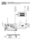
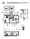
ATS “HS” Type Transfer Switch
Conductor sizes must be adequate to handle the
maximum current to which they will be subjected to,
based on the 75°C column of tables, charts, etc. used
to size conductors. The installation must comply fully
with all applicable codes, standards and regulations.
Before connecting wiring cables to terminals, remove
any surface oxides from the cable ends with a wire
brush. All power cables must enter the enclosure
through the knockouts. If not using the knockouts,
entry must be at or below knockouts. If ALUMINUM
conductors are used, apply corrosion inhibitor to
conductors. Tighten terminal lugs to the torque
values as noted in Section 1.2.2, and on the decal
located on the inside of the door. After tightening ter-
minal lugs, carefully wipe away any excess corrosion
inhibitor.
Use a torque wrench to tighten the conduc-
tors, being sure not to overtighten, or damage
to the switch base could occur. If not tightened
enough, a loose connection would result, caus-
ing excess heat which could damage the switch
base.
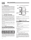
Connect power source load conductors to clearly
marked transfer mechanism terminal lugs as fol-
lows
1. Connect UTILITY (NORMAL) power source cables
to circuit breaker.
2. Connect EMERGENCY (STANDBY) source power
cables to transfer switch terminals E1, E2.
3. Connect customer LOAD leads to switch termi-
nals T1, T2.
Conductors must be properly supported, of approved
insulative qualities, protected by approved conduit,
and of the correct wire gauge size in accordance with
applicable codes.
Be sure to maintain proper electrical clearance
between live metal parts and grounded metal. Allow
at least 1/2 inch for 100-400 amp circuits.
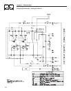
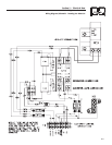
2.5 CONNECTING START CIRCUIT
WIRES
Control system interconnections consist of N1 and
N2, T1 and T2, and leads 23 and 194. Control system
interconnection leads must be run in a conduit that
is separate from the AC power lead. Recommended
wire gauge sizes for this wiring depends on the length
of the wire, as recommended below:
MAXIMUM WIRE LENGTH RECOMMENDED WIRE
SIZE
460 feet (140m) No. 18 AWG.
461 to 730 feet (223m) No. 16 AWG.
731 to 1,160 feet (354m) No. 14 AWG.
1,160 to 1,850 feet (565m) No. 12 AWG.
NOTE:
When this ATS is used with an air-cooled genera-
tor, the LOAD 1 and LOAD 2 wires are not used.
3.1 FUNCTIONAL TESTS AND
ADJUSTMENTS
Following transfer switch installation and inter-
connection, inspect the entire installation care-
fully. A competent, qualified electrician should
inspect it. The installation should comply strictly
with all applicable codes, standards, and regula-
tions. When absolutely certain the installation is
proper and correct, complete a functional test of
the system.
Perform functional tests in the exact order pre-
sented in this manual, or damage could be done
to the switch.
IMPORTANT: Before proceeding with functional tests,
read and make sure all instructions and information
in this section are understood. Also read the infor-
mation and instructions of labels and decals affixed
to the switch. Note any options or accessories that
might be installed and review their operation.
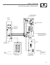
3.2 MANUAL OPERATION
DANGER
Do NOT manually transfer under load.
Disconnect transfer switch from all power sourc-
es by approved means, such as the main circuit
breaker(s).
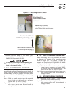
A manual HANDLE is shipped with the transfer
switch. Manual operation must be checked BEFORE
the transfer switch is operated electrically. To check
manual operation, proceed as follows:
1. Turn the generator’s AUTO/OFF/MANUAL switch
to OFF.
2. Turn OFF both UTILITY (service disconnect cir-
cuit breaker) and EMERGENCY (generator main
line to circuit breaker) power supplies to the
transfer switch.
3. Turn the GENERATOR DISCONNECT SWITCH
to the OFF position.
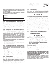
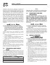
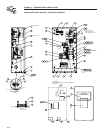
4. Note position of transfer mechanism main con-
tacts by observing the moveable contact carrier
arm. This can be viewed through the long narrow
slot in the inside cover of the ATS. The top of the
moveable contact carrier arm is yellow to be eas-
ily identified.
• Manual operation handle in the UP position -
LOAD terminals (T1, T2) are connected to UTIL-
ITY terminals (N1, N2).