


- 22 -GA-7N400E(-L) Motherboard
English
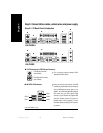
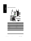
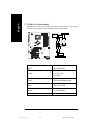
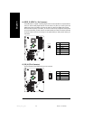
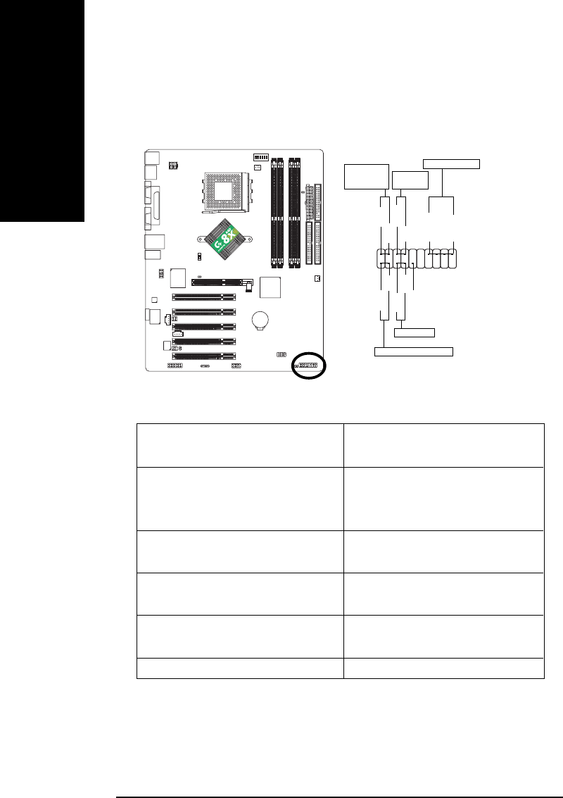
7) F_PANEL (2 x 10 pins Connector)
Please connect the power LED, PC speaker, reset switch and power switch etc. of your chassis
front panel to the F_PANEL connector according to the pin assignment above.
HD (IDE Hard Disk Active LED) Pin 1: LED anode(+)
(Blue) Pin 2: LED cathode(-)
SPK (Speaker Connector) Pin 1: VCC(+)
(Amber) Pin 2- Pin 3: NC
Pin 4: Data(-)
RES (Reset Switch) Open: Normal Operation
(Green) Close: Reset Hardware System
PW (Soft Power Connector) Open: Normal Operation
(Red) Close: Power On/Off
MSG(Message LED/ Power/ Sleep LED) Pin 1: LED anode(+)
(Yellow) Pin 2: LED cathode(-)
NC (Purple) NC
1
2
19
20
HD-
HD+
RES+
RES-
NC
IDE Hard Disk Active LED
Reset Switch
SPEAK-
MSG-
MSG+
PW-
PW+
Message LED/
Power/
Sleep LED
Speaker Connector
SPEAK+
1
1
11
1
Soft Power
Connector
7n400e_1001_q.p65 2003/7/17, ¤U¤È 02:5822