


Hardware Installation
3-3
2 +12V
3 SENSE
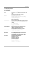
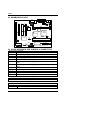
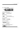
t Power FAN :Power FAN Power Connector
Pin No. Function
1 GND.
2 +12V
3 NC
t System FAN : System FAN Power Connector
Pin No. Function
1 GND.
2 +12V
3 NC
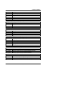
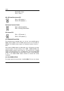
t JP7 : Wake on Lan
Pin No. Function
1 +5V SB
2 GND
3 Signal
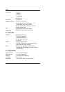
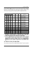
t IR : INFRARED Connector (IR) --(Optional)
Pin No. Function
1 IR Data Output
2 GND
3 IR Data Input
4 Signal
5 POWER (+)
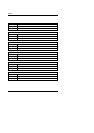
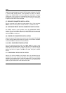
t JP8 : Onboard VGA Interrupt Function Selection
Pin No. Function
1-2 Close Onboard VGA Interrupt Function Disabled (Default).
2-3 Close Onboard VGA Interrupt Function Enabled.
t JP12 : Onboard VGA Function Selection
Pin No. Function
1-2 Close Onboard VGA Function Disabled.
2-3 Close Onboard VGA Function Enabled (Default).