


6ZMM
3-6
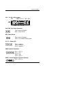
PIN 2-PIN3 : Short
PIN 4 : Data (−)
HD: IDE Hard Disk Active LED
PIN 1: LED anode (+)
PIN 2: LED cathode (
−
)
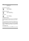
GN: Green Function Switch
Open : Normal operation
Short : Entering Green Mode
GD: Green LED
PIN 1 : LED anode (+)
PIN 2 : LED cathode (
−
)
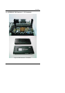
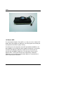
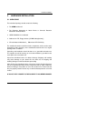
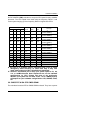
3.4. DRAM INSTALLATION
The mainboard can be installed with 8 / 16 / 32 / 64 / 128 / 256 MB 168 pins
DIMM module DRAM, and the DRAM speed must be 67~100 MHz for
SDRAM. The DRAM memory system on mainboard consists of bank 0 ,
bank 1.
Since 168 pins DIMM module is 64 bits width, using 1 PCS which can match
a 64 bits system. The total memory size is 8MB ~ 256MB SDRAM. The
DRAM installation position refer to Figure 3.1, and notice the Pin 1 of DIMM
module must match with the Pin 1 of DIMM socket. Insert the DRAM DIMM
module into the DIMM socket at Vertical angle. If there is a wrong direction
of Pin 1, the DRAM DIMM module couldn't be inserted into socket
completely.
3.5. CPU SPEED SETUP
The default system bus speed is 66 / 100MHz (SW2). The user can change
1
1