


20
English
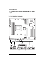
GA-3PXSL-RH Motherboard
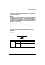
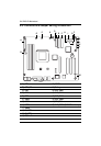
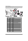
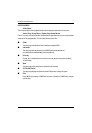
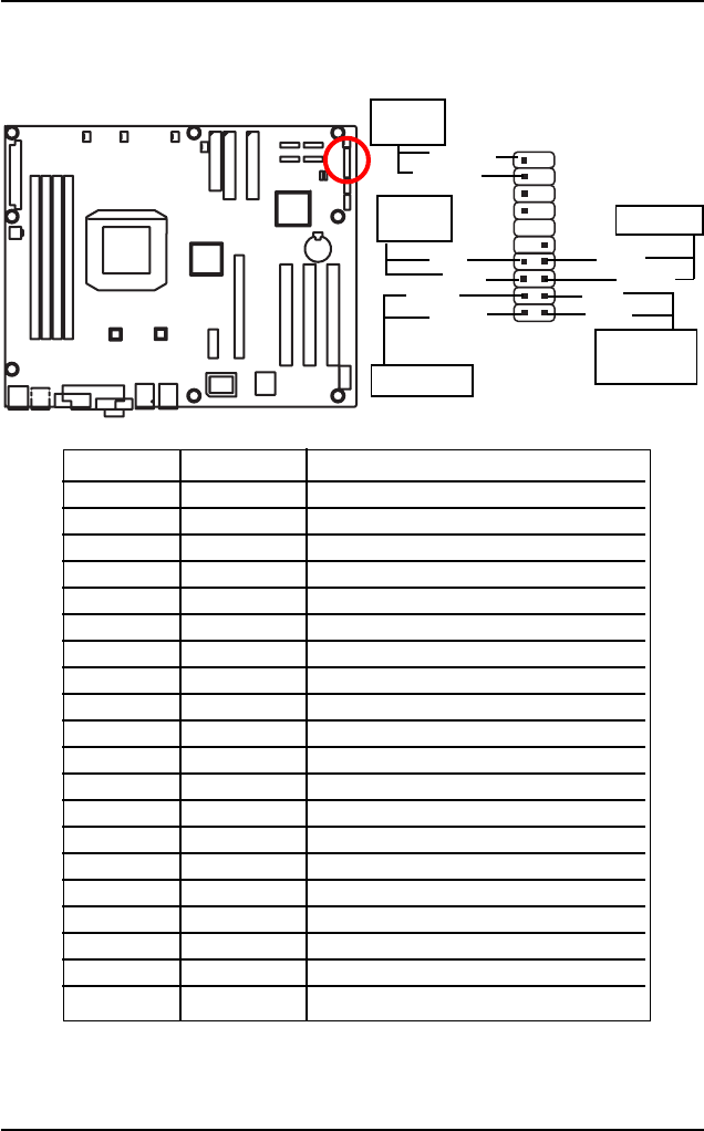
L ) F_Panel1 (2x10 Pins Front Panel Connectors)
1
2
Please connect the power LED, PC speaker, reset switch and power switch etc of your chassis
front panel to the front panel jumper according to the pin assignment below.
1920
HD+
HD-
IDE Hard Disk
Active LED
MSG+
MSG-
Message LED
PW+
PW-
Soft Power
Button
RES+
RES-
Reset Switch
SPEAK+
SPEAK-
Speaker
Connector
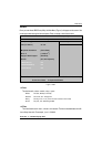
Pin No Signal Name Description
1 HD+ Hard Disk LED pull up (330 ohm)
2 MSG+ Message LED Signal (Pull up 330 ohm)
3 HD- Hard Disk Active LED Signal
4 MSG- Message Suspend LED (Blinking)
5 RES+ Front Panel Reset Button Signal
6 PW+ Front Panel Power On/Off Button
7 RES- Front Panel Reset Button Signal
8 PW- Front Panel Power On/Off Button
9 NC No Connect
10 KEY KEY
11 KEY KEY
12 KEY KEY
13 KEY KEY
14 KEY KEY
15 KEY KEY
16 KEY KEY
17 KEY KEY
18 KEY KEY
19 SPEAKER+ Speaker connector
20 SPEAKER- Speaker connector