


21
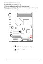
Connector Introduction
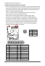
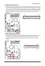
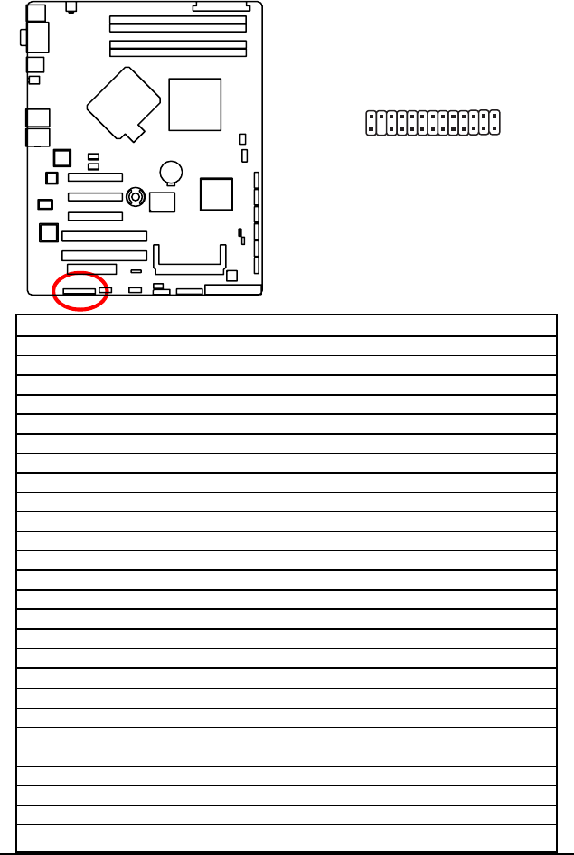
16 ) F_Panel (2X13 Pins Front Panel connector)
Please connect the power LED, PC speaker, reset switch and power switch of your chassis
front panel to the F_PANEL connector according to the pin assignment above.
26
13
2
1
Pin No. Signal Name Description
1. FP_PWR_LED Power LED Signal
2. P_5V_AUX P5V Stand By Power
3. Pin reomoved Pin removed
4. ID_LED- ID LED Signal cathode(-)
5. FP_PWR_LED- Power LED Signal cathode(-)
6. FP_ERR_LED- Error LED Signal cathode(-)
7. FP_HD_LED+ Hard Disk LED Signal anode (+)
8. FP_SYSRDY_LED+ System Fan Fail LED Signal anode (+)
9. GND Ground
10. FP_SYSRDY_LED- System Fan Fail LED Signal cathode(-)
11. BMC_MBMC_PWRBTN-No connect
12. P_3V3_AUX P3.3V Stand By Power
13. GND Ground
14. LANA_ACT- LAN1 access LED Signal cathode(-)
15. FP_RSTBTN- Reset button cathode(-)
16. SENSOR_SMBDAT1 SMBusData
17. GND LAN access LED Signal anode (+)
18. SENSOR_SMBCLK1 SMBusClock
19. FP_ID_SW- ID Switch Signal cathode(-)
20. CASEOPEN Chassis intrusion Signal
21. FP_SPKR- External speaker Signal cathode(-)
22. P_3V3_AUX P3.3V Stand By Power
23. FP_BUZ_STOP- Buzzer stop Signal cathode(-)
24. LANB_ACT- LAN2 access LED Signal cathode(-)
25. P_3V3_AUX P3.3V Stand By Power
26. NC No connect