


Hardware Installation- 25 -
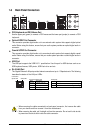
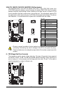
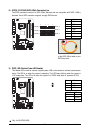
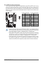
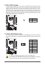
8) SATA2_0/1/2/3/4/5 (SATA 3Gb/s Connectors)
The SATA connectors conform to SATA 3Gb/s standard and are compatible with SATA 1.5Gb/s
standard. Each SATA connector supports a single SATA device.
Pin No. Definition
1 GND
2 TXP
3 TXN
4 GND
5 RXN
6 RXP
7 GND
Please connect the L-shaped end
of the SATA 3Gb/s cable to your
SATA hard drive.
7
SATA2_4
SATA2_5
1
SATA2_2
SATA2_3
1
7
SATA2_0
SATA2_1
7
7
1
1
Only for GA-EP45-UD3L.
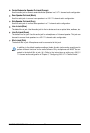
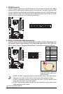
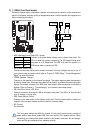
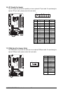
9) PWR_LED (System Power LED Header)
This header can be used to connect a system power LED on the chassis to indicate system power
status. The LED is on when the system is operating. The LED keeps blinking when the system is
in S1 sleep state. The LED is off when the system is in S3/S4 sleep state or powered off (S5).
Pin No. Definition
1 MPD+
2 MPD-
3 MPD-
System Status LED
S0 On
S1 Blinking
S3/S4/S5 Off
1