


GA-P31-ES3G Motherboard - 28 -
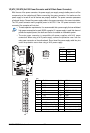
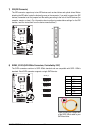
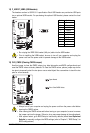
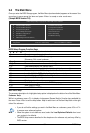
14) F_USB1/F_USB2 (USB Headers)
The headers conform to USB 2.0/1.1 specification. Each USB header can provide two USB ports
via an optional USB bracket. For purchasing the optional USB bracket, please contact the local
dealer.
Pin No. Definition
1 Power (5V)
2 Power (5V)
3 USB DX-
4 USB DY-
5 USB DX+
6 USB DY+
7 GND
8 GND
9 No Pin
10 NC
• Do not plug the IEEE 1394 bracket (2x5-pin) cable into the USB header.
• Prior to installing the USB bracket, be sure to turn off your computer and unplug the
power cord from the power outlet to prevent damage to the USB bracket.
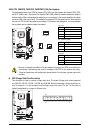
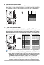
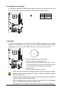
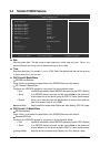
15) CLR_CMOS (Clearing CMOS Jumper)
Use this jumper to clear the CMOS values (e.g. date information and BIOS configurations) and
reset the CMOS values to factory defaults. To clear the CMOS values, place a jumper cap on the
two pins to temporarily short the two pins or use a metal object like a screwdriver to touch the two
pins for a few seconds.
Open: Normal
Short: Clear CMOS Values
• Always turn off your computer and unplug the power cord from the power outlet before
clearing the CMOS values.
• After clearing the CMOS values and before turning on your computer, be sure to remove
the jumper cap from the jumper. Failure to do so may cause damage to the motherboard.
• After system restart, go to BIOS Setup to load factory defaults (select Load Optimized
Defaults) or manually configure the BIOS settings (refer to Chapter 2, "BIOS Setup," for
BIOS configurations).
9
210
1