54
8.4. Connection Examples for
Gossen Müller & Weigert instruments
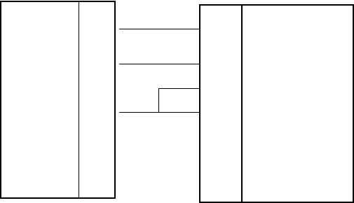
8.4.1. Connection of the IPP 144-40 GE to the DPM-MF
for the insertion of measured value into texts
For this configuration you must input and save the text as shown in section
7.4.1. of this manual.
The printer receives the measuring values via interface I / RS 232 C (also
possible via interface II). To selected the text see section 7.4.2 in this manual.
The relevant interface is the interface for which the parameters have to be set
in the menu program. The recommended configuration is: 8 data bits, no
parity, 1 stop bit, 9600 baud. With 7 bit, no parity, the sender must be set to
2 stop bits.
DPM...MF
IPP 144-40 GE
TxD
CTS
GND
OC 1
OC 2
3
4
6
5
7
2
8
1
5
RxD
RTS
GND
Sign.
GND
Interface 1


