


6 308703
Installation
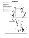
The installations in Fig. 2 are guides for selecting and installing system components. Contact your Graco distributor
for assistance in planning a system to suit your needs.
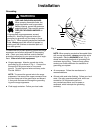
Mounting Automatic and Manual Models
Be sure the mounting surface can support the weight of the pump, surge suppressor, hoses, and accessories, and
the stress caused during operation.
D Mount the surge suppressor as close to the pump discharge as possible and upstream of equipment such as
valves, meters, filters, and so on. The surge suppressor should be installed within 10 pipe diameters of the
pump discharge.
D If you use a flexible connector from the pump to the piping system, the surge suppressor should be mounted to
the pump discharge manifold, and the flexible connector should be attached to the surge suppressor tee and
system piping.
D Because pressure is equal in all directions, the surge suppressor can be installed in any position, but the vertical
position shown in Fig. 2 is recommended for better draining. Fluids with high specific gravity or high viscosity,
settling of heavy material, and possible air entrapment further limit the mounting positions other than those
shown in Fig. 2.
NOTE: When you mount a plastic surge suppressor, do not overtighten by using a large pipe wrench near the
threads of the fluid inlet. The housing may crack if tightened too much. Hand tightening is recommended.
Connecting Automatic Models
D Connect the 1/4-in air supply hose to the 1/4 npt
connection on the top of the surge suppressor.
D The air pressure to the surge suppressor must be
greater than or equal to the pump discharge and/or
system pressure. For equal air pressure, you can
use a tee in the pump’s air supply line to run an air
line to the surge suppressor.
D For models with elastomer bladders, the tee must
be located in the pump’s air supply line before any
pump controller or instrumentation such as the
filter, regulator, or pump control valve.
D For models with PTFE bellows, the tee must be
located in the pump’s air supply line after any pump
controller or instrumentation such as the filter,
regulator, or pump control valve.
Connecting Manual Models
D Connect the 1/4-in air supply hose to the brass
one-way check valve on the top of the surge sup-
pressor.
D The air pressure to the surge suppressor must be
greater than or equal to the pump discharge and/or
system pressure. For equal air pressure, you can
use a tee in the pump’s air supply line to run an air
line to the surge suppressor.
D The tee must be located in the pump’s air supply
line before any pump controller or instrumentation
such as the filter, regulator, or pump control valve.