


308703 9
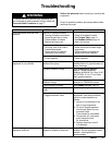
Troubleshooting
WARNING
To reduce the risk of serious injury whenever you
are instructed to relieve pressure, always follow the
Pressure Relief Procedure on page 7.
Relieve the pressure before checking or servicing the
equipment.
Check all possible problems and causes before disas-
sembling the pump.
PROBLEM
CAUSE SOLUTION
Surge suppressor does not hold
pressure.
Manual or automatic models:
–Leaking threaded connections
–Loose flange bolts or clamp
–Failed bladder or bellows
–Blocked air line to unit
–Check all threads for leaks.
–See Torque Table, page 11.
–See Bladder Failure, page 10.
–Use 1/4-in air line.
Automatic models only:
–One-way valve at air inlet is
installed backwards.
–Gauge shows no pressure,
and pump is not running.
–Arrow should point toward surge
suppressor.
–Pressure does not register on
gauge until pump is started.
Manual models only:
–Faulty regulator –Check regulator.
Dampening effect of surge
suppressor is not sufficient.
Surge suppressor installed incorrect
distance from pump
Surge suppressor should be
installed within 10 pipe diameters of
pump discharge.
Improper pressure charge See Charging and Startup,
page 8. Surge suppressor
pressure should be 2 to 10 psi (0.01
to 0.07 MPa, 0.1 to 0.7 bar) lower
than system pressure.
Surge suppressor does not hold
pressure charge.
See surge suppressor does not hold
pressure in PROBLEM column.
Failed bladder or bellows See Bladder Failure, page 10.
Surge suppressor too small for
pump
Install larger surge suppressor.
Automatic models only:
Plugged automatic valve
Remove pressure from surge
suppressor, and check automatic
valve for proper operation as
follows:
1. Leave air line attached to top
half of surge suppressor.
2. Fill top of surge suppressor
with enough water to cover
automatic valve.
There should be no bubbles.
3. Dump water out, and gently
push automatic valve.
Air should flow.
4. Replace automatic valve if
it is defective.
There is leaking around surge
suppressor fluid inlet.
PTFE sealing tape or paste is
needed on threads of fluid inlet.
Apply PTFE tape or paste to
threads. Do not overtighten plastic
models. Hand tightening is
recommended.