


SERIES 41 AND 81 MODUTROL IV™ MOTORS
63-2187—3 4
Accessories (continued):
4074EZE Bag Assembly with parts to provide CE compliance.
7617ADW Crank Arm approximately 0.75 in. shorter than
7616BR Crank Arm. Can rotate through downward position
and clear motor base without requiring adapter bracket.
ES650-117 Explosion-Proof Housing encloses motor for use
in explosive atmospheres. Not for use with Q5001 (or any
other valve linkages). Order separately from O-Z/Gedney
Inc. To order, contact: O-Z/Gedney, Nelson Enclosures and
Controls, (918) 641-7381 or (918) 641-7374; or write to:
O-Z/Gedney, Nelson Enclosures and Controls
P.O. Box 471650
Tulsa, OK 74147-1650
Requires Honeywell 7617DM Coupling.
Q100 Linkage connects Modutrol
®
motor to V51 Butterfly
Valve. Requires the 220738A Adapter Bracket (packed
with TRADELINE Modutrol IV motors).
Q5001 Bracket and Linkage Assembly connects Modutrol
motor to a water or steam globe valve.
Q605 Damper Linkage connects motor to damper. Includes
motor crank arm.
Q607 External Auxiliary Switch controls auxiliary equipment
as a function of motor position.
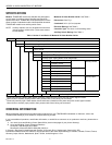
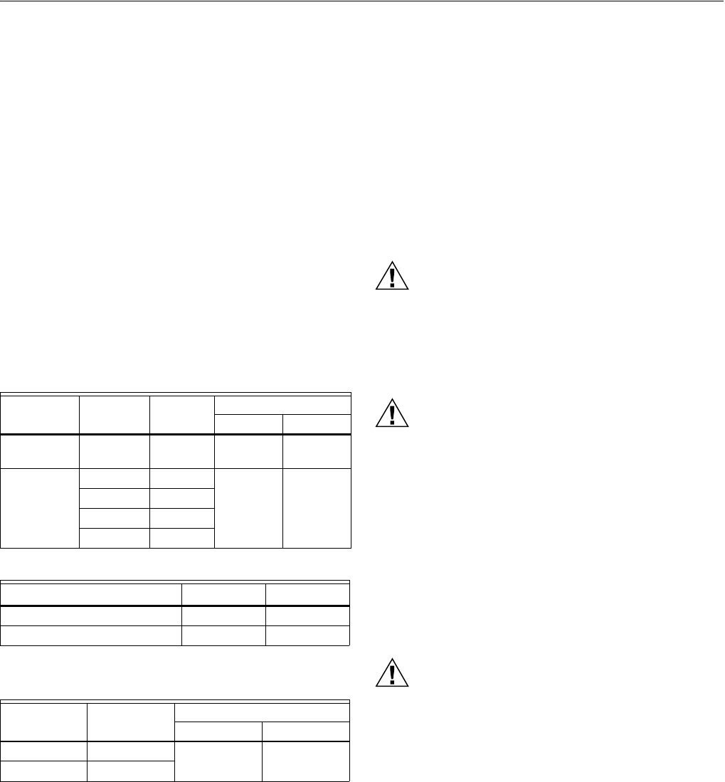
Table 2. Electrical Ratings.
Table 3. Auxiliary Switch Ratings.
a
40 VA pilot duty, 120/240 Vac on opposite contact.
Table 4. Torque and Timing.
INSTALLATION
When Installing this Product...
1. Read these instructions carefully. Failure to follow them
could damage the product or cause a hazardous
condition.
2. Check the ratings given in the instructions and on the
product to make sure the product is suitable for your
application.
3. Installer must be a trained, experienced service
technician.
4. After installation is complete, check out product
operation as provided in these instructions.
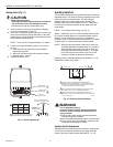
CAUTION
Electrical Shock or Equipment Damage Hazard.
Can shock individuals or short equipment
circuitry.
Disconnect all power supplies before installation.
Motors with auxiliary switches can have more than
one disconnect.
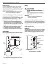
CAUTION
Equipment Damage Hazard.
Can damage the motor beyond repair.
Never turn the motor shaft by hand or with a wrench.
Forcibly turning the motor shaft damages the gear
train and stroke limit contacts.
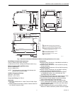
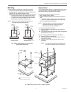
Location
Allow enough clearance for installing accessories and motor
servicing when selecting a location (see Fig. 1). If located
outdoors, use liquid-tight conduit connectors with the junction
box to provide NEMA 3 weather protection. If mounted
outdoors in a position other than upright, install a 4074ERU
Weatherproofing Kit and liquid-tight connectors to provide
NEMA 3 protection.
CAUTION
Motor Damage Hazard.
Deteriorating vapors and acid fumes can damage
metal parts.
Install motor in areas free of acid fumes and other
deteriorating vapors.
In excessive salt environments, mounting base and screws
should be zinc or cadmium plated, not stainless steel or
brass. Use the 220738A Adapter Bracket for mounting on
these surfaces.
Voltage (at
50/60 Hz)
Current
Draw (A)
Power Consumption
(VA) (W)
Without
Transformer
24 0.86 21 20
With Internal
Transformer
24 1.25 30 25
120 0.25
208 0.14
240 0.13
One Contact Rating
a
(Amps) 120 V 240 V
Full Load 7.2 3.6
Locked Rotor 43.2 21.6
Torque lb-in.
(N-m)
Timing (sec.)
90° Stroke 160° Stroke
M8175 25 (2.8) 30 60
Other models 60 (6.8)