


SERIES 41 AND 81 MODUTROL IV™ MOTORS
7 63-2187—3
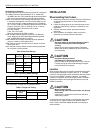
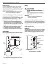
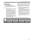
Fig. 6. Typical connections for Series 41 Motors.
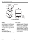
Fig. 7. Typical connections for Series 81 Motors.
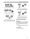
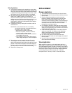
Fig. 8. Power connections for Series 41 Line Voltage
Motors controlling two-position outside air dampers.
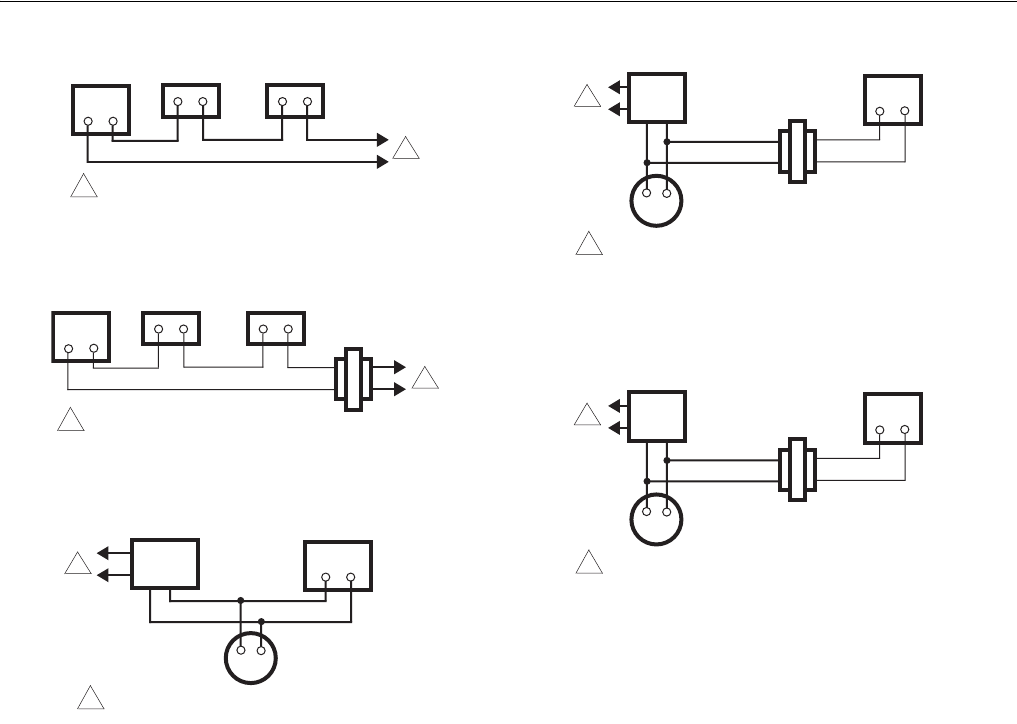
Fig. 9. Power connections for Low Voltage Motors
controlling two-position outside air dampers.
Fig. 10. Wiring connections for Series 81 Motors
controlling two-position pre-heat coil valves.
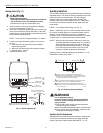
SETTINGS AND ADJUSTMENTS
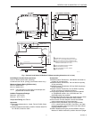
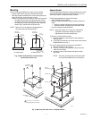
Stroke Setting
On adjustable stroke motors, the stroke is field adjustable and
can be set between 90° and 160°. A mechanical adjustment
(cam) establishes the fully open (clockwise, viewed from the
power end) and fully closed positions of the motor shaft
(see Fig. 2). TRADELINE motors are factory set for 160°.
IMPORTANT
— Detach linkage from motor before adjusting stroke.
— Instructions are for normally closed models. Reverse
for normally open.
Before Setting Stroke
1. Remove top cover from motor.
2. Disconnect controller from motor.
MOTOR
1
1
M806
A
THERMOSTAT LIMIT CONTROL
POWER SUPPLY. PROVIDE DISCONNECT MEANS
AND OVERLOAD PROTECTION AS REQUIRED.
MOTOR
1
M807A
THERMOSTAT LIMIT CONTROL
TRANSFORMER
1
POWER SUPPLY. PROVIDE DISCONNECT MEANS
AND OVERLOAD PROTECTION AS REQUIRED.
MOTOR
1
M808A
MOTOR
STARTER
BLOWER
1
POWER SUPPLY. PROVIDE DISCONNECT MEANS
AND OVERLOAD PROTECTION AS REQUIRED.
24V
MOTOR
1
M809A
TRANSFORMER
MOTOR
STARTER
BLOWER
POWER SUPPLY. PROVIDE DISCONNECT MEANS
AND OVERLOAD PROTECTION AS REQUIRED.
1
24V
MOTOR
1
M809A
TRANSFORMER
MOTOR
STARTER
BLOWER
POWER SUPPLY. PROVIDE DISCONNECT MEANS
AND OVERLOAD PROTECTION AS REQUIRED.
1