


- 4 -
2.3 Technical data
The requirements of the following are met:
2006/95/EC, 2004/108/EC
The product fulfils the guidelines and standards for CE labelling.
HF outputs:
Modulators A / B / C / D
Channels: C 02 … C 69
(incl. S 03 … S 14 and S 16 … S 41)
Frequency range: 48.25 MHz … 855.25 MHz
Modulation method: CCIR, PAL B/G
Output level: typ. 86 dBµV
Output impedance: 75 Ω, nominal
Video signal-to-noise ratio: typ. 55 dB
Video frequency response: 20 Hz … 5 MHz
Audio frequency response: 40 Hz … 15 kHz
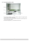
Connections:
HF output: 1 F socket
Connection strip (20-pin):
Supply voltages and control circuits
AV input:
26-pin
pin socket
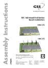
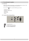
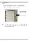
2.4 Description
The modulator modules contain four modulators, which convert existing video
and audio signals into PAL B/G signals in the C 02 … C 69 channel range via
the AV interface.
The modulators are labelled (analogue to the channel strips) as “A”, “B”, “C”
and “D”, and can be individually programmed. Four LEDs indicate if the respec-
tive modulator is switched on (LED illuminates) or off.
The audio and video signals being fed in through the 26-pin socket of the
modulator module are modulated onto the carrier frequencies (channels) which
have been selected. The HF output signals are sent through the HF output on the
modulator module to the output collector. The levels of the HF output signals are
adjustable by software.
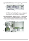
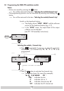
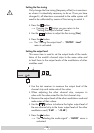
When the head-end station is switched on, the two-line LC display shows the
“SETUP” menu and the software version of the control unit. The head-end station
total output level can be adjusted in this menu.
If the modulator modules are not detected by the head-end station you can up-
date the head-end station’s operating software via the head-end station’s 9-pin