- 6 -
•
Open the housing of the head-end station in accordance with the assembly
instructions for the STC 160.
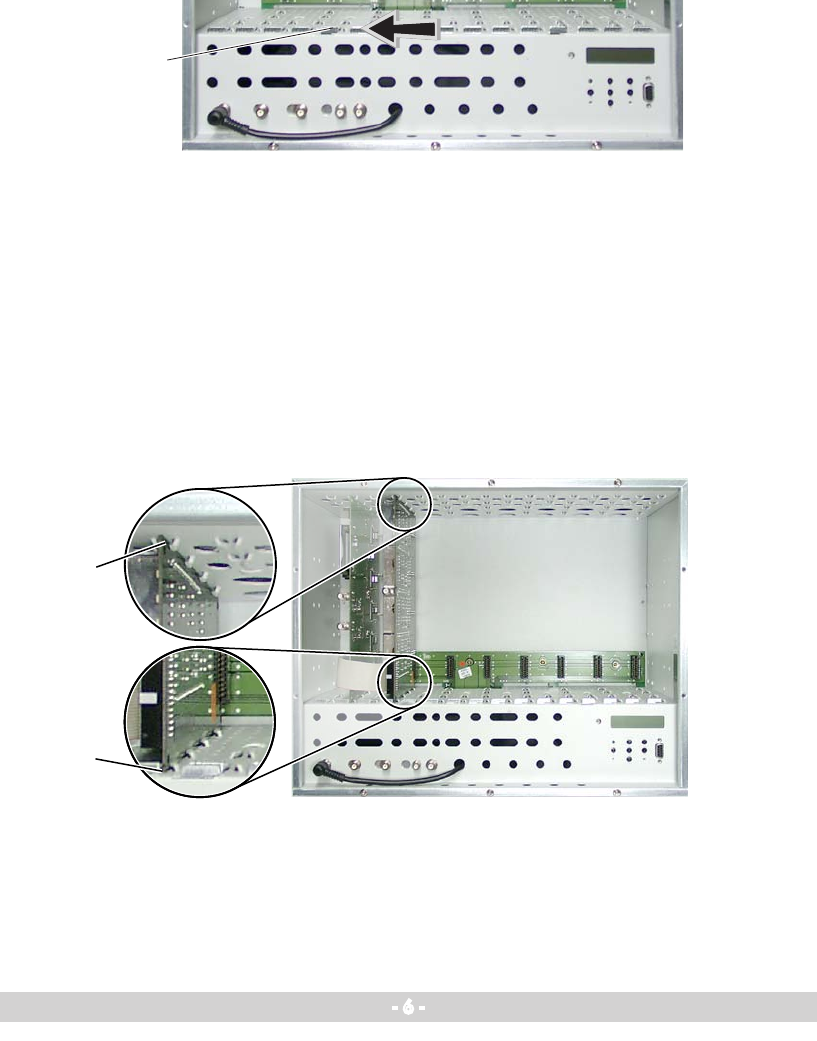
•Openthelockingdevice1 in the direction of the arrow (fig. 1).
—> Slots 1 (digital module) and 2 (modulator module) are shown in fig-
ure 2. The open slot in between (without a contact strip on the board at
the rear wall of the housing) is intended for an add-on module.
•InsertthemodulatormoduleingroovesA and B (fig. 2) of an open slot on
the right hand side of the associated digital module or an add-on module.
•Gentlyslidethemodulatormoduleintothehead-endstationandensurethat
it makes contact with the contact strip on the board at the rear wall of the
housing.
Fig. 1
Fig. 2


