CUC 7350
Schaltungsbeschreibung / Circuit Description
2 - 8 GRUNDIG Service
is passed on for further processing, and in the other, the signal is
applied to the sync separator.
The sync separator produces the horizontal and the vertical synchron-
ising pulses from the Y-signal. The horizontal synchronising signal is
passed on to the ϕ1 phase control, the vertical synchronising signal is
used to start the line counter for vertical synchronisation.
3.10 Line Oscillator
With this IC concept, the line frequency is generated completely inside
the line oscillator. The IC is not connected to external components so
that it is not necessary to adjust the free running horizontal and the free
running vertical frequency.
3.11 ϕ1 Phase Control
The ϕ1 phase control stage is for controlling the frequency. This stage
adjusts the frequency of the line oscillator to that of the line synchron-
ising pulse. For this, the frequency of the line synchronising pulse is
compared with the line oscillator frequency.
A ϕ1 phase control stage defines the time constant of the control
voltage which is fed out at Pin 43. The control voltage shifts the line
oscillator until the frequencies are equal.
3.12 ϕ2 Phase Control
The ϕ2 phase control stage is for controlling the phase position of the
line drive pulse. This determines the phase off-set between the line
synchronising pulses and the actual position of the electron beam.
Dependent on the circuit components and the beam current, the delay
time between the external signal, the trigger signal and the actual
reaction of the line output stage is different. These differences are
compensated for by the ϕ2 control.
To identify the position of the electron beam the line flyback pulse from
the line output transformer is applied to IC34015-(41).
3.13 The Super Sand Castle - SSC
The 3-level SSC signal IC34015-(41) is a composite pulse consisting
of the line flyback, the field flyback, and the burst key pulses. The line
flyback pulse (H-Sync) is fed through CT50020, CR50013 to IC34015.
The field flyback and burst key pulses are generated inside the IC.
3.14 Setting of the Cut-Off Voltage
An automatic cut-off controlling stage ensures that the static working
points of the CRT are held stable. For this, IC34015 feeds out a pulse
to the R, G, B cathodes during the lines 23, 24 and 25 to measure the
beam current of each system (approx. 10µA). The cut-off current
during the measuring lines is fed via the resistor CR34056 to
IC34015-(18). The IC compares this voltage with an internal reference
value to determine the working point for the black level of the video
output stages and the cut-off voltage of the CRT respectively.
3.15 The HDR Output Stage
Following an internal amplification the horizontal drive signal for the
line output transistor is provided at IC34015-(40).
hat, wird das Y-Signal zur weiteren Signalverarbeitung und für das
Amplitudensieb aufgeteilt.
Das Amplitudensieb erzeugt den Horizontal- und Vertikalsynchron-
impuls aus dem Y-Signal. Das Horizontal-Synchronsignal gelangt nun
auf die ϕ1-Regelung, das Vertikal-Synchronsignal startet den Zeilen-
zähler für die Vertikalsynchronisation.
3.10 Zeilenoszillator
Bei diesem IC-Konzept generiert der Zeilenoszillator die Zeilenfrequenz
vollständig intern. Er besitzt keine externen Bauteile. Somit sind weder
die freilaufende Horizontal- noch die freilaufende Vertikalfrequenz
einzustellen.
3.11 ϕ1-Regelung
Die ϕ1-Regelung stellt eine Frequenzregelung dar. Damit wird der
Horizontal-Oszillator auf die Frequenz des Zeilensynchronsignals
geregelt. Hierzu wird die Frequenz des Zeilensynchronsignals mit der
Frequenz des Horizontal-Oszillators verglichen.
Ein ϕ1-Regelkreis definiert die Zeitkonstante der Regelspannung, die
an Pin 43 ausgeben wird. Die Regelspannung verschiebt den Zeilen-
oszillator solange, bis die Frequenzen übereinstimmen.
3.12 ϕ2-Regelung
Die ϕ2-Regelung ist die Phasenregelung. Sie stellt den Phasenbezug
zwischen dem Zeilensynchronsignal und der tatsächlichen Position
des Elektronenstrahls her. Je nach Schaltung und Strahlstrom haben
wir eine unterschiedliche Verzögerungszeit zwischen dem Außen-,
dem Triggersignal und der tatsächlichen Reaktion der Zeilenendstufe.
Diese Unterschiede werden durch die ϕ2-Regelung ausgeglichen.
Für die Strahlposition ist der Zeilenrückschlagimpuls vom Zeilentrafo
am IC34015-(41) angeschlossen.
3.13 Supersandcastle SSC
Das 3-pegelige Supersandcastlesignal IC34015-(41) ist ein Kombi-
Impuls bestehend aus dem Horizontal- Vertikal- und Burstauftastimpuls.
Der Zeilenrückschlagimpuls (H-Sync) wird über CT50020, CR50013
dem IC34015 zugeführt. Der Bildrückschlag- und Burstkeyimpuls
werden im IC generiert.
3.14 Cut-Off-Einstellung
Die statischen Arbeitspunkte der Bildröhre werden über die Cut-Off-
Automatik stabil gehalten. Dazu gibt der IC34015 in der Zeile 23, 24
und 25 einen Impuls an die R, G, B-Kathoden aus, um den Strahlstrom
jedes Systems zu messen (ca. 10µA). Der Cut-Off-Strom während der
Meßzeilen wird über Widerstand CR34056 dem IC34015-(18) zuge-
führt. Der IC vergleicht diesen Strom mit einem internen Referenzwert
und bildet daraus den Arbeitspunkt für den Schwarzwert der Video-
endstufen bzw. Cut-Off Spannung der Bildröhre.
3.15 HDR-Endstufe
Nach interner Verstärkung steht an IC34015-(40) das Horizontale
Ansteuersignal für den Zeilenendstufentransistor.
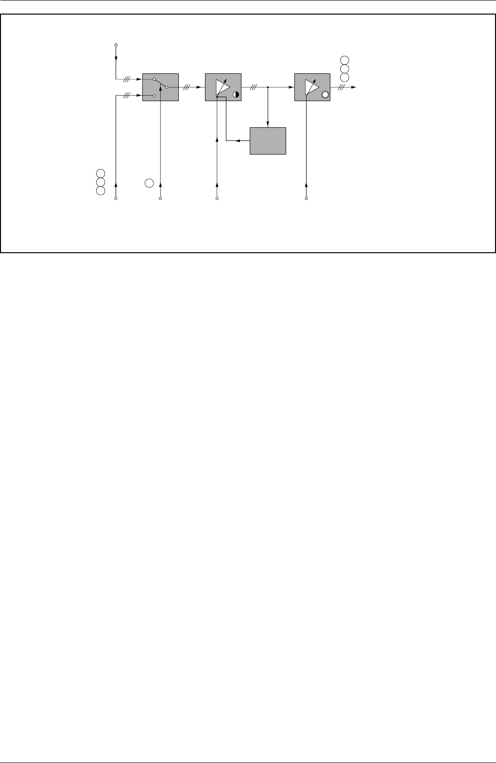
RGB Ausgangsverstärker
RGB Output Amplifier
RGB intern
Internal RGB
RGB von Scart
oder Videotext
RGB from Scart
or Videotext
Data Kontrast
Contrast
Helligkeit
Brightness
RGB extern
External RGB
RGB zur
Bildrohrplatte
RGB to the
CRT panel
Spitzenweiß
Begrenzung
Peak White
Limiting
23
24
25
26
19
20
21


