CUC 7350
Schaltungsbeschreibung / Circuit Description
GRUNDIG Service 2 - 9
3.16 Vertikal-Ablenkung
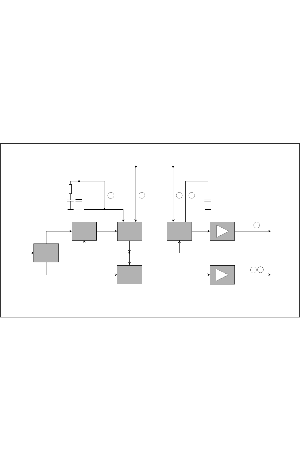
Der Vertikal-Generator wird in diesem IC-Konzept durch einen Zeilen-
zähler ersetzt.
Werden keine Synchronimpulse empfangen, so läuft der Zeilen-
oszillator unsynchronisiert. Aus dem Zeilenoszillator leiten wir den
"Vertikaloszillator" ab. Es muß nur die Anzahl der Zeilen gezählt
werden. Nachdem der Zähler 312 Zeilen festgestellt hat, wird ein
Bildsynchronsignal ausgegeben. Damit ist sowohl die horizontale als
auch die vertikale Ablenkung ohne externe Synchronisation sicherge-
stellt.
Wird ein Synchronsignal empfangen, dann läuft zunächst der Zeilen-
oszillator synchron. Der Zeilenzähler liefert auch hier ein vertikales
Ablenksignal. Kommt nun ein Vertikalsynchronsignal, wird der
Sägezahngenerator nicht mehr vom Zeilenzähler sondern direkt vom
Vertikalsynchronsignal getriggert .
Der Sägezahngenerator besteht aus einer Kostantstromquelle, die
einen externen Kondensator auf- und wieder entlädt. Die Ladezeit gibt
das Vertikalsynchronsignal vor.
3.17 Koinzidenz
Die Koinzidenz-Information erhält der Prozessor über den I
2
C-Bus
vom TV Signalprozessor IC34015.
3.16 The Field Deflection Stage
In this circuit concept, the field sync generator has been replaced by
a line counter.
When no synchronising signals are received the line oscillator is free
running. From this line oscillator the "vertical oscillator" is derived by
counting the number of lines. After having counted 312 lines, the
counter feeds out a field sync signal so that the horizontal and also the
vertical deflection is achieved without using an external synchronising
signal.
On reception of a synchronising signal, the line oscillator will first be
synchronised. In this case too, the line counter supplies a field
deflection signal. As soon as a field synchronising signal is obtained
the saw-tooth generator will no longer be triggered by the line counter
but directly by the field sync signal.
The saw-tooth generator is made up of a constant current source which
is used to charge and discharge an external capacitor. The charging
period is determined by the field sync signal.
3.17 Coincidence
The coincidence information to be sent to the processor is obtained
from the TV signal porcessor IC34015 via the I
2
C-bus.
Zeilenoszillator
Line Oscillator
FBAS
CCVS
Amplitudensieb
Sync Separator
ϕ
1
Zeilenzähler
Line Counter
V-Sync
H-Sync
ϕ
2
HDR
VDR
43 36
Enable Oszillator
Enable Oscillator
41 42
Regelzeitkonstante
für die
ϕ 1-Regelung
Flyback
40
Control Time Constant
for
ϕ 1-Control
46
47
Horizontal- und Vertikal-Synchronisation und Ablenkung
Horizontal- and Vertical Synchronisation and Deflection


