


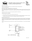

Installation Procedure
1. Be sure that all power to the load has been disconnected by turning off the circuit breaker.
2. If applicable, remove the faceplate from the existing wall switch, remove the existing wall switch from the wall box, and
disconnect the wires from the existing wall switch. Identify the “Line”, "Neutral", "Load" and “Traveler” (if applicable) wires.
3. Remove ¾” of insulation from each of the wires on the HAI UPB™ Wall Switch. Install the HAI UPB™ Wall Switch by
connecting wires per wiring configuration shown in Figure 5.
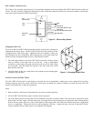
4. Install any optional HAI Auxiliary Switch per wiring configuration shown in Figure 5.
5. After all connections have been made, be certain that all wire connectors are firmly attached and there is no exposed copper.
6. Gently place the wires and HAI UPB™ Wall Switch into the wall box with the LED at the top of device. Using the supplied
screws, attach the HAI UPB™ Wall Switch to the wall box.
7. Before installing the faceplate, restore power to the circuit.
8. After testing the HAI UPB™ Wall Switch and Auxiliary Switch for proper local operation (Table 1), install a Decora-style
faceplate over each switch.
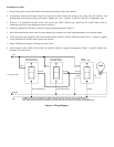
LINE
NEUTRAL
37A00 (OPTIONAL)
AUXILIARY SWITCH
AUXILIARY SWITCH
37A00 (OPTIONAL)
40A00
HAI Relay Switch
BLACK BLACK
BLACK
REDWHITE
YELLOWYELLOW
*BLUE AND/OR GRAY*BLUE AND/OR GRAY
YELLOW
*CONNECTING THE BLUE AND/OR GRAY WIRE TO NEUTRAL SETS THE COLOR OF THE LED INDICATOR.
CONNECT BLUE FOR BLUE INDICATOR, GRAY FOR RED INDICATOR, OR BOTH FOR MAGENTA INDICATOR.
BLUE AND/OR GRAY WIRE MAY BE CONNECTED TO NEUTRAL OR EARTH GROUND. NEUTRAL IS RECOMMENDED.
GREEN
Line 120VAC, 60Hz
LOAD
Figure 4 – Wiring Diagram