


2
Models: PMD 1 & PMD 2
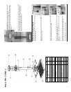
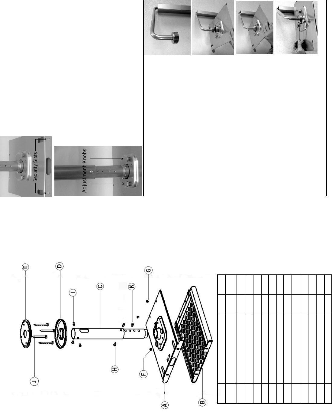
Part Description Qty.
Mount Assembly Hard-
ware
A Top Projector Plate 1
B Bottom Projector Plate 1
C Pipe Drop Assembly 1
D Plastic Cover 1
E Ceiling Plate 1 Bag
F Hex Screw: ¼”-20 X ¼” 1 (d)
G Screw: ¼”-20 X 3/8” 2 (c)
H Hex Screw: ¼”-X 5/8” 4 (d)
I Hex Screw: ¼”-X ½” 6 (d)
J Lag Bolt: 5/16” X 3” 4 (e)
K Plastic Plugs 14 (b)
Hex Wrench 1 (d)
7
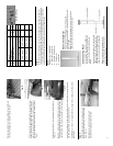
Important: Always secure projector plates by installing 3/8”
screws (G) into holes on front edge of plates.
Additional security can be provided by installing small pad-
locks through security slots at the rear of the projector plates.
(Fig. 12)
Fig. 12
Attach cables to the projector. Turn projector ON, and make pitch
and keystone adjustments as per the projector manufacturers
instructions. For additional pitch/tilt, use the three adjustment
knobs on top of the PMD mount (Fig. 13).
Fig. 13
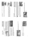
Wall Mounting with OmniMount PMD-WM
Install the OmniMount PMD-WM wall mount to the wall as per
the instructions. (Fig. 14)
Separate top and bottom projector mounting plates (A&B), by
sliding them apart. (Fig. 2)
Loosely thread top projector mounting plate (A) onto threaded
portion of wall mount coupler. (Fig. 15 & 16)
Thread ¼” hex head set screw (F) into side of pipe collar, on top
projector mounting plate (A). (Fig. 17)
Note: If necessary, screw in tilt knob to gain access to the set
screw hole.
Position top projector mounting plate into desired orientation
(horizontal or vertical), and then tighten set screw (F).
Proceed to Step 4 to complete the installation.
Fig. 14
Fig. 15
Fig. 16
Fig. 17