


Page 5SKU 45146 For technical questions, please call 1-800-444-3353.
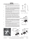
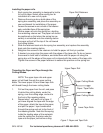
Figure 6. Cutting Blade Installation.
Mount upper blade with the cutting edge
down, and lower blade with cutting edge up.
Rear View of Complete Upper Assembly Back View.
frame as shown in
Figure 5
.
10. Repeat step 9 using the hole below the hand grip
in the right rear frame.
11. Repeat step 9 using the holes located on the front
frames just above the large bottom tray.
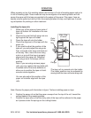
12. Select one of the bolts you have just installed,
and thread a wing nut and washer halfway onto
the bolt. Thread the wing nut on so that the flat
side of the wing nut faces to the inside of the frame
assembly.
See detail photo.
13. Insert the metal bushings into the center of the
tape roll holders.
14. Place one tape roll holder with the metal bush-
ing installed onto one of the bolts. Face the tape
roll holder so the flanges are nearest to the frame.
Thread on a washer and wing nut to the bolt as
shown in
the detail photo
. Tighten against the tape
roll holder.
15. Repeat steps 12- 14 to install the remaining three
tape roll holders.
16. Install both cutting blades (H) onto the front
frames as shown in
Figure 6
. Mount upper blade
with the cutting edge down, and lower blade with
cutting edge up. Assemble using two screws, four
washers, and two nuts per paper cutting blade.
Carefully fit a long spring (L) on the bottom of the
front edge of the lip of the paper cutting blade
(H). Secure the hooks on each end of the spring
in the holes on the paper cutting blade. Repeat
with the other blade. See lower half of
Figure 6
.
17. Attach the small side tray to the right side of the
assembly using two bolts, nuts and washers.
18. Attach the towel holder to the left side of the as-
sembly. Insert the ends of the rack into the holes
on the side of the assembly, rotating them upward
to “hook” the rack into the frame.
REV 05/05
Figure 5. Tape Roll Holder
Bolt Assembly
Tape Roll Holder Detail Photo
H
L