


iv Service Manual
Reference Information................................................................................................... 5-1
Password Removal Policy.............................................................................................................5-1
Hewlett-Packard Display Quality Statement.................................................................................5-2
Service Notes and Obsolete Parts .................................................................................................5-4
Figures
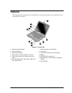
Figure 1-1. Front View.........................................................................................................................1-3
Figure 1-2. Back View.........................................................................................................................1-4
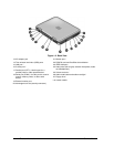
Figure 1-3. Bottom View .....................................................................................................................1-5
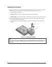
Figure 1-4. Resetting the Notebook.....................................................................................................1-9
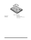
Figure 1-5. Replaceable Module Diagram.........................................................................................1-14
Figure 2-1. Disassembly Flow..............................................................................................................2-3
Figure 2-2. Removing the Battery........................................................................................................2-4
Figure 2-3. Removing an SDRAM Module.........................................................................................2-5
Figure 2-4. Removing the Mini-PCI Card ...........................................................................................2-6
Figure 2-5. Removing the Hard Disk Drive.........................................................................................2-7
Figure 2-6. Removing the Hard Disk Drive Tray ................................................................................2-8
Figure 2-7. Removing the Keyboard Cover.......................................................................................2-11
Figure 2-8. Removing the Speaker Assembly....................................................................................2-12
Figure 2-9. Removing the Keyboard..................................................................................................2-14
Figure 2-10. Removing the Switchboard PCA ..................................................................................2-15
Figure 2-11. Removing the CD/DVD Drive......................................................................................2-16
Figure 2-12. Removing the Display Assembly..................................................................................2-18
Figure 2-13. Removing the Top Case ................................................................................................2-21
Figure 2-14. Removing the Floppy Drive ..........................................................................................2-23
Figure 2-15. Removing the I/R PCA..................................................................................................2-26
Figure 2-16. Removing the Heatsink (with Fan)................................................................................2-27
Figure 2-17. Removing the CPU Module ..........................................................................................2-30
Figure 2-18. Removing the Motherboard...........................................................................................2-32
Figure 2-19. Example of Serial Number Label..................................................................................2-35
Figure 2-20. Replacing the Antennas.................................................................................................2-36
Figure 2-21. Removing a PCMCIA Door..........................................................................................2-36
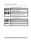
Figure 2-22. Boot-Block Jumper........................................................................................................2-38
Figure 3-1. Basic Troubleshooting Steps.............................................................................................3-2
Figure 4-1. Exploded View..................................................................................................................4-2