11-11
Using Authorized IP Managers
Building IP Masks
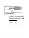
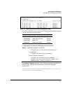
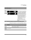
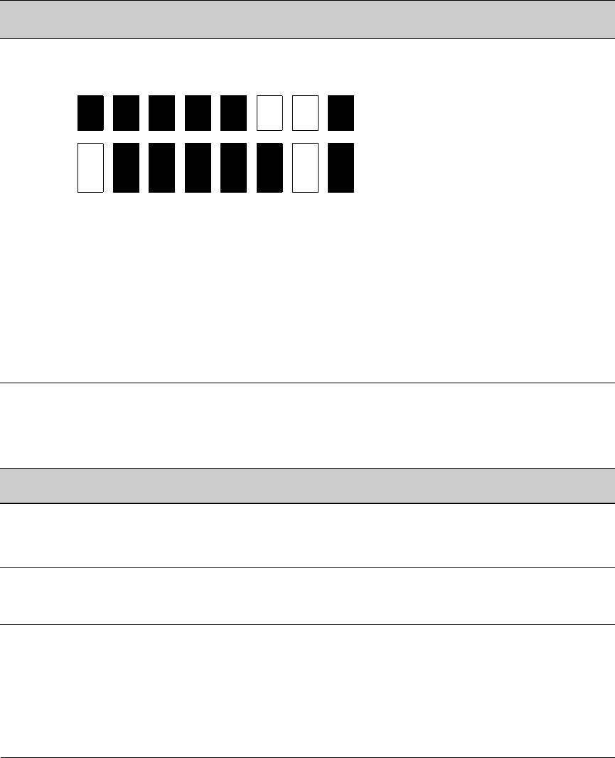
Figure 11-6. Example of How the Bitmap in the IP Mask Defines Authorized Manager Addresses
Additional Examples for Authorizing Multiple Stations
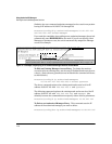
4th Octet of IP Mask:
4th Octet of Authorized IP Address:
249
5
Bit Numbers Bit
7
Bit
6
Bit
5
Bit
4
Bit
3
Bit
2
Bit
1
Bit
0
Bit Values 128 64 32 16 8 4 2 1
4th Octet of
IP Mask (249)
Bits 1 and 2 in the mask are “off”, and bits 0 and 3
- 7 are “on”, creating a value of 249 in the 4th octet.
Where a mask bit is “on”, the corresponding bit
setting in the address of a potentially authorized
station must match the IP Authorized Address
setting for that same bit. Where a mask bit is “off”
the corresponding bit setting in the address can be
either “on” or “off”. In this example, in order for a
station to be authorized to access the switch:
• The first three octets of the station’s IP address
must match the Authorized IP Address.
• Bit 0 and Bits 3 through 6 of the 4th octet in the
station’s address must be “on” (value = 1).
• Bit 7 of the 4th octet in the station’s address
must be “off” (value = 0).
• Bits 1 and 2 can be either “on” or “off”.
This means that stations with the IP address
13.28.227.X (where X is 121, 123, 125, or 127) are
authorized.
4th Octet of
IP Authorized
Address (125)
Entries for Authorized
Manager List
Results
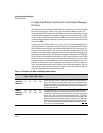
IP Mask 255 255 0 255 This combination specifies an authorized IP address of 10.33.xxx.1. It could be
applied, for example, to a subnetted network where each subnet is defined by the
third octet and includes a management station defined by the value of “1” in the
fourth octet of the station’s IP address.
Authorized
Manager IP
10 33 248 1
IP Mask 255 238 255 250 Allows 230, 231, 246, and 247 in the 2nd octet, and 194, 195, 198, 199 in the 4th octet.
Authorized
Manager IP
10 247 100 195


