


Removal and replacement procedures
Maintenance and Service Guide 4–53
✎
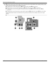
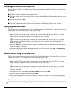
Steps 4 and 5 apply to computer models equipped with graphics subsystems with UMA memory. See steps 2
and 3 for instructions on removing the fan/heat sink assembly on computer models equipped with graphics
subsystems with discrete memory.
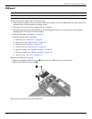
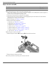
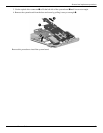
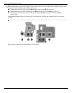
4. Loosen the four captive Phillips PM2.0×7.0 screws 1 that secure the fan/heat sink assembly to the
system board.
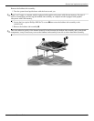
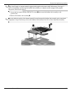
5. Remove the fan/heat sink assembly 2.
✎
Due to the adhesive quality of the thermal material located between the fan/heat sink assembly and system board
components, it may be necessary to move the fan/heat sink assembly from side to side to detach the assembly.