


Operations 13
2.
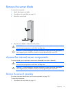
Remove the server blade (on page 12).
3. Place the server blade on a flat, level work surface with the bezel facing away from you.
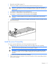
CAUTION: The jackscrews control the unseating and seating of critical system connectors.
Failure to use the jackscrews to remove and install the server B assembly can cause the system
boards to fail.
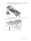
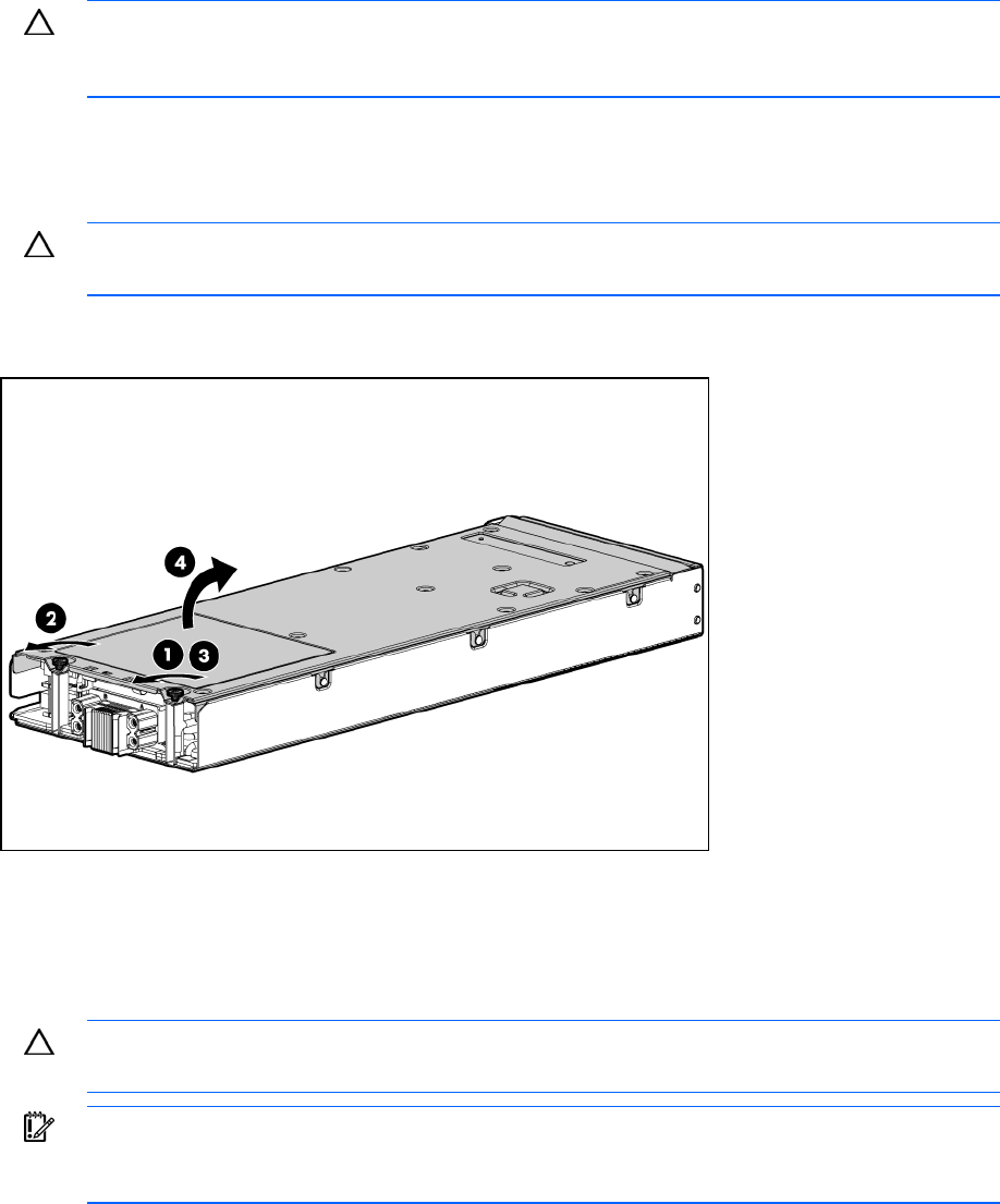
4. Turn jackscrew 1 approximately six turns counterclockwise.
5. Turn jackscrew 2 counterclockwise until the threads are fully disengaged.
6. Turn jackscrew 1 counterclockwise until the threads are fully disengaged.
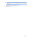
CAUTION: To prevent damage to the server blade, do not apply pressure to the enclosure
connector.
7. Lift the server B assembly from the server A assembly, and then place it on the work surface with the
system board facing up.
Install the server B assembly
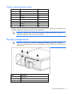
For access component identification, see "Access components (on page 10)."
1. Engage the front edge of the server B assembly with the front edge of the server A assembly.
CAUTION: To avoid possible damage to mezzanine card cables, route any cables so that
they do not become pinched when the server B assembly is installed.
IMPORTANT: To avoid possible damage to the serial label pull tab, extend the serial label
pull tab approximately 1 cm (0.4 in) before installing the server B assembly on the server A
assembly.
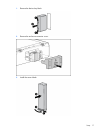
2. Lower the server B assembly onto the server A assembly.
3. Align the signal and power connectors on the server B assembly with the corresponding connectors
on the server A assembly.