


6
HP Vectra VL 5/xxx Series 5 PC
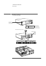
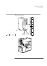
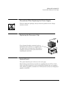
Precautions When Replacing the System Board
Precautions When Replacing the System Board
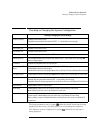
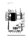
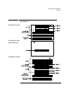
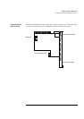
Switch Functions of the System Board Switches
1-4,7
Processor frequency (see the information printed on the system board)
5
Password:
Open = enabled (default)
Closed = disabled / clear User and Administrator passwords
6
Prevents changes to the PC’s configuration (in CMOS) in the
Setup
program:
Open = normal (default — you can change the configuration in the
Setup
program)
Closed = clear CMOS (to reload the
Setup
program defaults and to prohibit changes to the
Setup
program)
8
Not used
9
Keyboard space-bar power-on:
Open = disabled
Closed = enabled (default)
10
Product identification:
Open = normal operation (default)
Closed = clear the product identification field in the CMOS memory
After replacing the system board, flash the System ROM with the latest
version of the System BIOS. Then reconfigure the PC using the Setup
program.
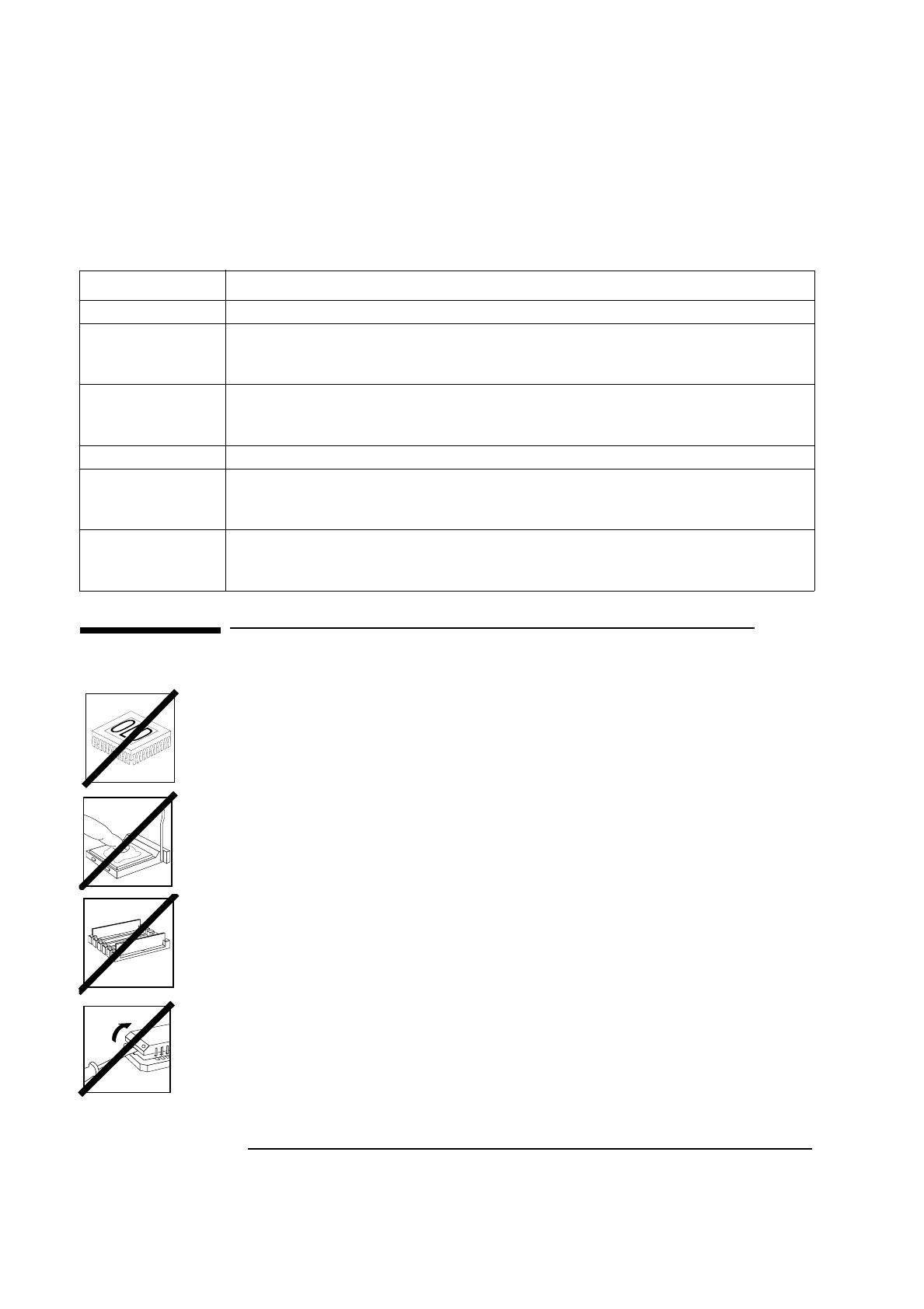
Do not remove the thermal interface material between the processor and
the heat-sink. To do so would affect the cooling of the processor.
This interface material may stick the processor and heat-sink together.
Do not attempt to separate them. Manipulate them as a single unit.
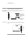
Do not reinstall the memory modules haphazardly. There are three memory
banks, which can be filled in any order, each comprising a pair of sockets.
Different banks can contain memory module pairs of different sizes or types.
However, in each bank which is occupied, you must install a pair of identical
modules.
Always use the specific extraction tool (PLCC IC Extraction, part number
5041-2553) when removing the video memory upgrade chips.