


B - Verification and Calibration
56
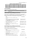
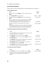
5. Set the output current to its full scale value (see Table B-2).
6. Divide the voltage drop across the current monitor by its
resistance to convert the value to amperes. Record this value and
the current reading on the front panel display.
Readings within high current
limits (see tables B-3,4, 5 or 6).
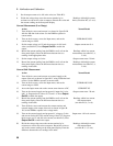
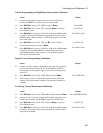
Current Measurement (Low Range)
Action Normal Result
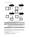
7. Turn off the dc source and connect it as shown in figure B-1B
with the 400 ohm load resistor. Set the DMM to operate in
current mode.
8. Turn on the dc source, access the Input menu, and set the
current range to LOW.
CURR:RANG LOW
9. Set the output voltage to 0 V and the current to its full scale
value (see table B-2). Press Output On/Off to enable the
output.
Output current near 0 A.
10. Record the current reading from the DMM as well as from the
front panel display. Enter the difference between the two
readings in the appropriate table.
Readings within low current
measurement (see table B-3, 4,
5 or 6).
11. Set the output voltage to 8 volts. Output current near +20 mA.
12. Record the current reading from the DMM as well as from the
front panel display. Enter the difference between the two
readings in the table.
Readings within high current
measurement (see table B-3, 4,
5 or 6).
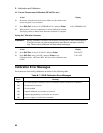
Current Sink Measurement
Action Normal Result
13. Turn off the dc source and connect an external supply to the
output of the unit as shown in figure B-1C using a 400 ohm load
resistor. Set the DMM to operate in current mode.
14. Turn on the dc source, access the Input menu, and set the
current range to LOW.
CURR:RANG LOW
15. Access the Input menu and set the current sense detector to DC. CURR:DET DC
16. Turn on the external supply and program its’output for 8 volts
and 1 A. Program the dc source to 0 V and 1 A. Press Output
On/Off to enable the output.
Output current near −20 mA.
17. Record the current reading from the DMM as well as from the
front panel display. Enter the difference between the two
readings in the table.
Readings within low current
sink measurement
(see table B-3,4, 5 or 6).
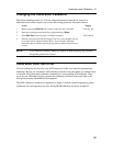
18. Turn off the dc source and connect the current monitor and
external supply to the output of the unit as shown in figure B-
1D. Set the DMM to operate in dc voltage mode.
19. Turn on the external supply and program its’ voltage to 5 volts
and current for the full scale current rating of the UUT. Program
the dc source to 0 V and full scale current (see table B-2). Press
Output On/Off to enable the output.
Output near −full scale current.
20. Divide the voltage drop across the current monitor by its
resistance to convert the value to amperes. Record this value as
well as the current reading on the front panel display. Enter the
difference between the two readings in the table.
Readings within high current
sink measurement
(see table B-3, 4, 5 or 6).