


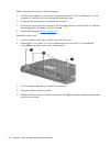
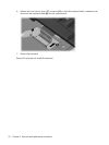
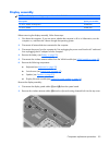
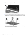
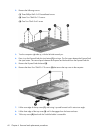
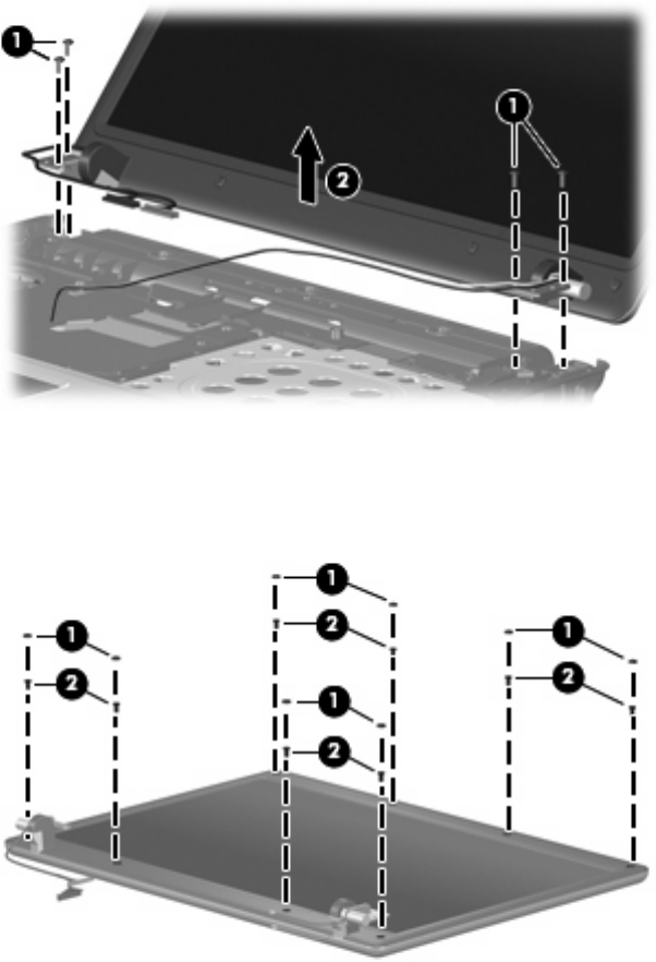
3. Remove the four Torx T8M2.5×7.0 screws (1) that secure the display assembly to the computer.
4. Lift the display assembly (2) straight up and remove it.
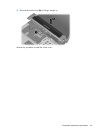
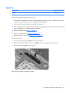
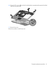
5.
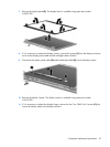
If it is necessary to replace the display bezel, display inverter, or display hinges, remove the eight
rubber screw covers (1) and the eight Torx T8M2.5×6.0 screws (2) that secure the display bezel to
the display assembly. The rubber screw covers are available in the Rubber Kit, spare part number
456616-001.
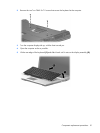
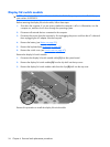
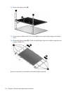
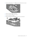
6. Flex the inside edges of the left and right sides (1) and the top and bottom sides (2) of the display
bezel until the bezel disengages from the display enclosure.
56 Chapter 4 Removal and replacement procedures