


Installation and configuration procedures 6
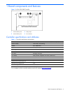
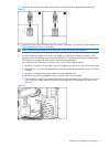
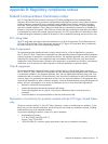
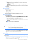
7. Attach the other end of the I2C able to the connector on the internal drive cage backplane board (2).
Figure 2-1
8. Install drives in the internal SATA drive bay of the server, if necessary. The 6-Port SATA RAID Controller can
support logical drives of up to 2 TB capacity.
NOTE: To determine the number of drives required for a particular RAID level, see page 17.
9. Use SATA cables (provided with the server or available as a separate kit) to connect the ports on the
controller to the corresponding ports on the server backplane. (To determine the location of the backplane
SATA connector in a particular server model, see the server documentation.)
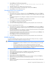
In HP ProLiant ML350 Generation 4p servers, use two 4x/1x SATA cables as follows:
a. Attach the 4x connector of one cable to the lower backplane port (lower four SATA drives in the cage).
b. Attach the four 1x connectors (labeled P0–P3) at the other end of the cable bundle to ports 0–3 of the
controller.
c. Attach the 4x connector of the other cable to the upper backplane port.
d. Attach the two connectors labeled P0 and P1 to ports 4 and 5 of the controller.
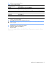
e. Position cables P2 and P3 in the cable bundle from the upper backplane port so that they are out of the
way. In this server model, these two cables are inactive (they are not connected to any drives in the
drive bay).
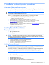
Figure 2-2
10. Close the computer cabinet.