


7.
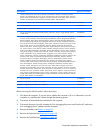
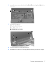
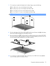
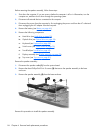
If it is necessary to replace the display bezel or display hinges, remove the following:
(1) Four rubber screw covers on the display bezel top edge
(2) Two rubber screw covers on the display bezel bottom edge
(3) Four Torx T8M2.5×6.0 screws on the display bezel top edge
(4) Two Torx T8M2.5×7.0 screws on the display bezel bottom edge
NOTE: See Display inverter on page 48 for display inverter replacement instructions.
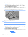
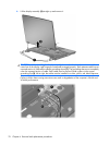
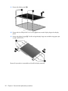
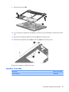
8. Flex the inside edges of the left and right sides (1) and the top and bottom sides (2) of the display
bezel until the bezel disengages from the display enclosure.
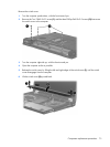
9. Remove the display bezel (3). The display bezel is available using spare part numbers 455078-001
(for use with computer models equipped with WLAN and WWAN capability) and 452215-001 (for
use with computer models equipped with only WLAN capability).
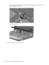
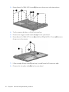
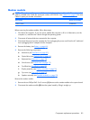
10. If it is necessary to replace the display hinges, remove the six Torx T8M2.5×6.0 screws (1) that
secure the display panel to the display enclosure.
Component replacement procedures 79