


Hardware and Software Installation Procedure
Step 1: Access the system card bay
3
Hardware and Software Installation Procedure
These instructions apply to AB465A PCI-X 2-Port 2 Gigabit Fibre Channel and 2-Port Gigabit Ethernet
combination cards which can operate on HP-UX 11i v 1.0 of December 2004 or HP-UX 11i v 2.0 of
September 2004 or later. If your system is running HP-UX 11i v 1.0, you can find the 11i v 1.0 LAN
and fibre channel driver bundles on the December 2004 OE distribution media. For 11i v 1.0, you
can either load the entire OE or just the two driver bundles for this card. If loading this product
on 11i v 2.0, you need to load the entire HP-UX 11i v 2.0 September 2004 OE from the distribution
media and you will automatically get the correct LAN and fibre channel driver bundles.
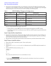
Note: if your LAN card was factory installed (ordered on product option 0D1), you do not need to perform the
following hardware and software installation steps though you still need to configure the card’s IP address as
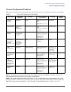
well as set other parameters and options such as those mentioned in Table 2 The Network Configuration
Worksheet.
These AB465A combination cards can be added to your system or replaced without the need to shut down or
reboot the system--a process called online addition and replacement (OLAR). The following instructions
assume you are not performing online addition and replacement.
Step 1: Access the system card bay
• If the system is running, first, issue the sync command. Then shut down the system by executing:
shutdown -h. Respond “y” to the continue to shutdown prompt.
• Wait for the system to shut down completely, and then power off the system by pressing the system off
button. Ensure that the system is grounded.
• Open the system to gain access to the PCI backplane.
• Select an empty PCI or PCI-X slot and remove the slot cover. The card can operate in PCI as well as PCI-X
mode. Some servers have “shared” slots. If you put this card in a shared slot that is shared with a slower
card, both cards will then operate at the slower card’s speed.
Step 2: Install the card
• Check the latest support matrix to see the systems that support this card, how many cards per system,
and if any software updates are needed, The support matrix is available on the web at http://docs.hp.com
under “Networking and Communications.”
• Observe the antistatic precautions. HP recommends wearing ESD straps when installing the card.
• Record the serial number and MAC address located on the card for future reference. The MAC address
labelled on the card refers to LAN port A. Add 1 to obtain the MAC address for LAN port B. For fibre
channel, also record the card’s Port and Node worldwide names (WWN). The WWN labelled on each card
refers to WWN for FC port 1 (the left port). Add 2 to obtain the WWN for FC port 2 (the right port).
• Grasp the card by its edges or faceplate with both hands, insert the card into the slot, and firmly but
gently press the card in until it is fully seated.
• Secure the card and reassemble the system.
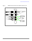
Step 3: Connect the card to the network
• Attach the connector from a LAN cable to the card (Figure 1 on page 11). Do the same for the second port.
For 1000Base-T, cabling must be Cat 5 UTP or better with RJ-45 connectors. For operating distances,
refer to the “Cable Specifications” section of this document. Note: LAN A is the bottom RJ-45 connector.