


Installing an External 5.25-inch or 3.5-inch Drive
NOTE: The system does not support Parallel ATA (PATA) optical drives.
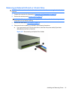
1. Prepare the computer for disassembly (Preparation for Disassembly on page 74).
2. Remove the access panel (
Access Panel on page 75).
WARNING! To reduce risk of personal injury from hot surfaces, allow the internal system
components to cool before touching.
3. Remove the front bezel (Front Bezel on page 76).
4. If you are installing a drive in a bay covered by a bezel blank, remove the bezel blank. See
Removing Bezel Blanks on page 77 for more information.
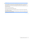
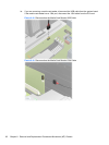
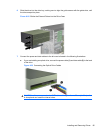
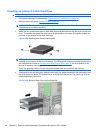
5. Install four M3 metric guide screws in the lower holes on each side of the drive. HP has provided
eight extra M3 metric guide screws on the front of the chassis, under the front bezel. The M3 metric
guide screws are black. Refer to
Installing and Removing Drives on page 88 for an illustration of
the extra M3 metric guide screws location.
CAUTION: Use only 5-mm long screws as guide screws. Longer screws can damage the internal
components of the drive.
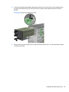
NOTE: When replacing the drive, transfer the four M3 metric guide screws from the old drive to
the new one.
Figure 8-21 Installing Guide Screws (Optical Drive Shown)
94 Chapter 8 Removal and Replacement Procedures Microtower (MT) Chassis