


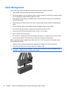
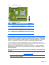
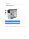

Figure 8-5 DIMM Socket Locations
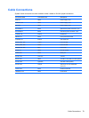
Table 8-1 DIMM Socket Locations
Item Description Socket Color
1 XMM1 socket, Channel A (populate fourth) White
2 XMM2 socket, Channel B (populate third) White
3 XMM3 socket, Channel A (populate second) Black
4 XMM4 socket, Channel B (populate first) Black
NOTE: A DIMM must occupy the black XMM4 socket. Otherwise, the system will display
a POST error message indicating that a memory module must be installed in the wrong
socket.
CAUTION: You must disconnect the power cord and wait approximately 30 seconds for the power to
drain before adding or removing memory modules. Regardless of the power-on state, voltage is always
supplied to the memory modules as long as the computer is plugged into an active AC outlet. Adding
or removing memory modules while voltage is present may cause irreparable damage to the memory
modules or system board. If you see an LED light on the system board, voltage is still present.
The memory module sockets have gold-plated metal contacts. When upgrading the memory, it is
important to use memory modules with gold-plated metal contacts to prevent corrosion and/or oxidation
resulting from having incompatible metals in contact with each other.
Static electricity can damage the electronic components of the computer or optional cards. Before
beginning these procedures, ensure that you are discharged of static electricity by briefly touching a
grounded metal object.
When handling a memory module, be careful not to touch any of the contacts. Doing so may damage
the module.
1. Prepare the computer for disassembly (Preparation for Disassembly on page 74).
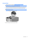
2. Remove the computer access panel (
Access Panel on page 75).
WARNING! To reduce risk of personal injury from hot surfaces, allow the internal system
components to cool before touching.
Memory 81