


3.
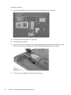
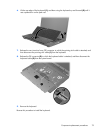
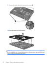
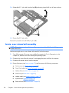
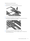
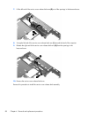
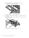
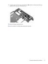
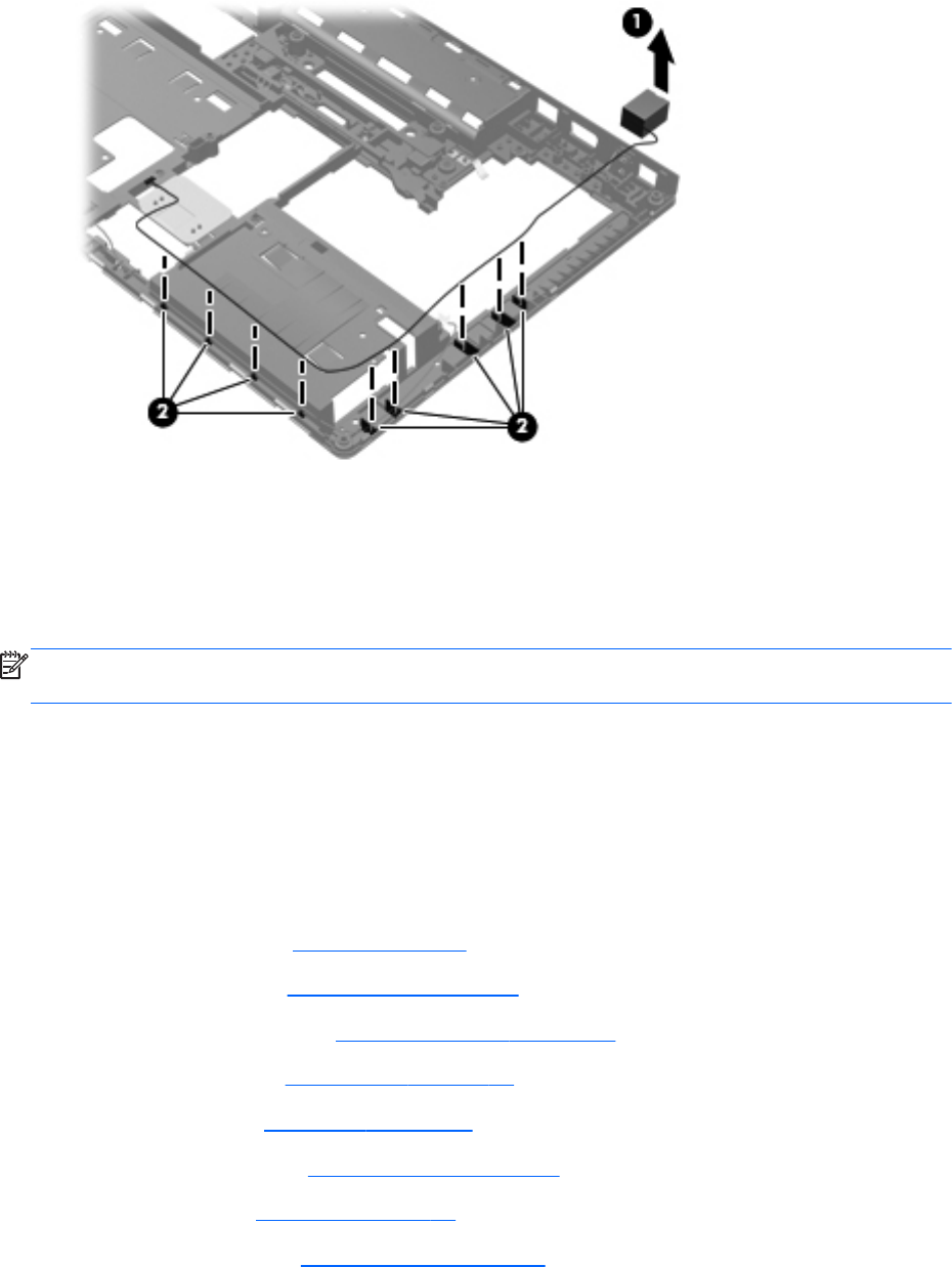
Release the RJ-11 jack cable from the clips (2) and routing channel built into the base enclosure.
4. Remove the RJ-11 jack cable.
Reverse this procedure to install the RJ-11 jack cable.
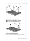
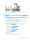
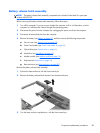
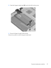
Service cover release latch assembly
NOTE: The service cover release latch assembly components are included in the Latch Kit, spare part
number 684339-001.
Before removing the service cover release latch assembly, follow these steps:
1.
Turn off the computer. If you are unsure whether the computer is off or in Hibernation, turn the
computer on, and then shut it down through the operating system.
2. Disconnect the power from the computer by unplugging the power cord from the computer.
3.
Disconnect all external devices from the computer.
4. Remove the battery (see
Battery on page 57), and then remove the following components:
a. Service cover (see
Service cover on page 59)
b. Smart Card reader (see
Smart Card reader on page 60)
c. Optical drive (see
Optical drive on page 61)
d. Hard drive (see
Hard drive on page 65)
e. Modem module (see
Modem module on page 74)
f. Keyboard (see
Keyboard on page 76)
g. Base enclosure (see
Base enclosure on page 80)
86 Chapter 4 Removal and replacement procedures