


Processor
NOTE: The processor spare part kit includes thermal material.
Description Spare part number
Intel Core2 Duo T9800 2.93 GHz with 6-MB L2 cache and 1066-MHz FSB 507951-001
Intel Core2 Duo T9600 2.80 GHz with 6-MB L2 cache and 1066-MHz FSB 507955-001
Intel Core2 Duo T9550 2.66 GHz with 6-MB L2 cache and 1066-MHz FSB 507953-001
Intel Core2 Duo T9400 2.53 GHz with 6-MB L2 cache and 1066-MHz FSB 507954–001
Intel Core2 Duo T6600 2.20 GHz with 2-MB L2 cache and 800-MHz FSB 513593-001
Intel Core2 Duo T6400 2.00 GHz with 2-MB L2 cache and 800-MHz FSB 513592-001
Intel Core2 Duo T5800 2.00 GHz with 2-MB L2 cache and 800-MHz FSB 515040-001
Intel Pentium Dual-Core T4200 2.00 GHz with 1-MB L2 cache and 800-MHz FSB 513599-001
Intel Pentium Dual-Core T3400 2.16 GHz with 1-MB L2 cache and 1066-MHz FSB 509549–001
Intel Core Duo P8700 2.53 GHz with 3-MB L2 cache and 1066-MHz FSB 507960-001
Intel Core Duo P8600 2.40 GHz with 3-MB L2 cache and 1066-MHz FSB 507961-001
Intel Core Duo P8400 2.26 GHz with 3-MB L2 cache and 1066-MHz FSB 507962-001
Intel Core Duo P7450 2.13 GHz with 3-MB L2 cache and 1066-MHz FSB 507122-001
Intel Celeron T1600 1.66 GHz with 1-MB L2 cache and 667-MHz FSB (for use only with computers
equipped with UMA graphics memory subsystems)
501894-001
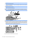
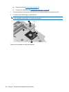
Before removing the processor, follow these steps:
1. Shut down the computer. If you are unsure whether the computer is off or in Hibernation, turn the
computer on, and then shut it down through the operating system.
2. Disconnect all external devices connected to the computer.
3. Disconnect the power from the computer by first unplugging the power cord from the AC outlet and
then unplugging the AC adapter from the computer.
4. Remove the battery (see
Battery on page 54).
5. Remove the following components:
a. Hard drive (see
Hard drive on page 63).
b. Optical drive (see
Optical drive on page 57).
c. Switch cover and keyboard (see
Switch cover and keyboard on page 70).
d. Display assembly (see
Display assembly on page 75).
e. Top cover (see
Top cover on page 85).
f. USB board (see
USB board on page 92).
Component replacement procedures 101