


Removal and replacement procedures
Maintenance and Service Guide 4–19
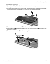
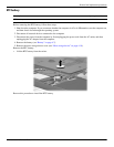
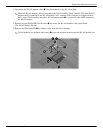
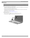
3. Disconnect the WLAN antenna cables 1 from the terminals on the WLAN module.
✎
The black WLAN antenna cable is connected to the WLAN module “Main” terminal. The white WLAN
antenna cable is connected to the WLAN module “Aux” terminal. If the computer is equipped with an
802.11a/g/n WLAN module, the yellow WLAN antenna cable 2 is connected to the middle terminal on
the WLAN module.
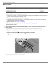
4. Remove the two Phillips PM2.0×4.0 screws 3 that secure the WLAN module to the system board.
(The WLAN module tilts up.)
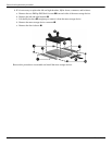
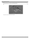
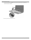
5. Remove the WLAN module 4 by pulling it away from the slot at an angle.
✎
WLAN modules are designed with a notch 5 to prevent incorrect insertion into the WLAN module slot.