


Removal and Replacement Procedures
Maintenance and Service Guide 5–73
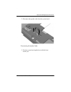
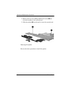
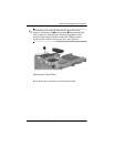
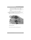
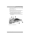
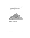
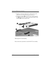
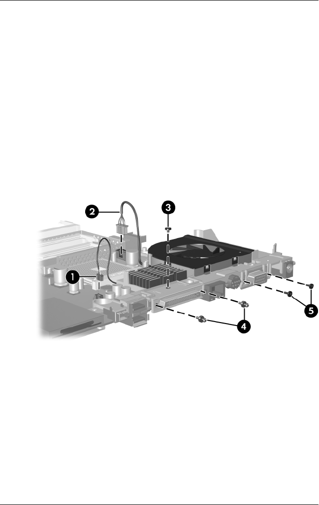
2. Disconnect the fan cable 1 and the power connector cable 2
from the system board.
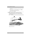
3. Remove the following screws:
3 One Phillips PM2.5×4.0 screw that secures the expansion
port bracket and fan assembly to the system board
4 Two slotted M1.5×9.0 screws on each side of the
expansion port 2 connector that secure the expansion port
bracket and fan assembly to the system board
5 Two Phillips PM2.5×7.0 screws on each side of the
external monitor connector that secure the fan assembly to
the system board
Removing the Fan Assembly Screws