


Display subcomponents (bezel, webcam, panel)
This section describes removing display subcomponents that do not require that you remove the
entire display assembly from the computer. You can remove the display bezel, webcam/microphone
module, and display panel while the display assembly is still attached to the computer.
To remove the remaining display subcomponents, including the hinge covers, hinges, cable,
antennas, and enclosure, you must remove the entire display assembly from the computer. See
Display assembly on page 71 for more information about removing the display assembly in its
entirety.
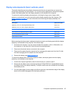
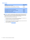
Description Spare part number
35.6-cm (14.0-in), HD, LED, BrightView display panel 685101-001
35.6-cm (14.0-in), HD, LED, Anti-glare display panel 694746-001
Display bezel (includes Mylar screw covers) 685081-001
HP TrueVision HD webcam/microphone module 694747-001
HP VGA webcam/microphone module 685112-001
Rubber display bumpers 685102-001
Before removing the display bezel, webcam/microphone module, and display panel while the display
assembly is still attached to the computer, follow these steps:
1. Shut down the computer. If you are unsure whether the computer is off or in Hibernation, turn
the computer on, and then shut it down through the operating system.
2. Disconnect all external devices connected to the computer.
3. Disconnect the power from the computer by first unplugging the power cord from the AC outlet
and then unplugging the AC adapter from the computer.
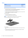
4. Remove the battery (see
Battery on page 34).
To remove the display bezel, webcam/microphone module, and display panel while the display
assembly is still attached to the computer:
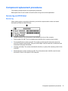
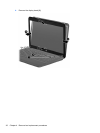
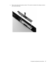
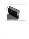
1. Position the computer right-side up with the front toward you, and then open it.
2. Remove the two Mylar screw covers (1) and the two Phillips PM2.5×4.0 screws (2) that secure
the display bezel to the display assembly. The Mylar screw covers are included with the display
bezel spare part kit.
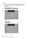
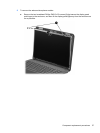
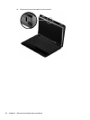
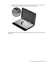
3. Flex the inside edges of the top edge, the left and right sides, and the bottom edge of the display
bezel until the bezel disengages from the display enclosure.
Component replacement procedures 35