


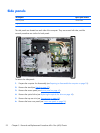

Front bezel and display panel
Description Spare part number
Front bezel 733500-001
Assembly kit for non-touchscreen models without a webcam (includes webcam cover for bezel) 733510-001
Assembly kit for touchscreen models without a webcam (includes webcam cover for bezel) 733511-001
Touch panel kit, with integrated touch glass 735208-001
Display panel – non-touchscreen models 735207-001
Plastic frame for models with a webcam (does not include glass) 733507-001
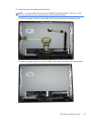
The front bezel is located on the front of the computer and is secured to the main system frame with 18
Torx screws.
Replacement bezels include the webcam shutter and capacitive sensor board. On models that do not
include a webcam, you must remove the shutter and install the webcam cover (Assembly kit) into the
slot in which the webcam would be installed.
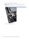
Display panels require a backlight cable specific to the manufacturer. Make sure you use the backlight
cable packaged with the display panel.
To remove the front bezel:
1. Remove the stand (see
Stand on page 37).
2. Prepare the computer for disassembly (see
Preparing to disassemble the computer on page 35).
3. Remove the access panel (see
Access panel on page 41).
4. Remove the optical drive (see
Replacing the optical disc drive on page 48).
5. Remove the top rear trim (see
Top rear trim on page 69).
6. Remove the lower rear panel (see
Lower rear panel on page 74).
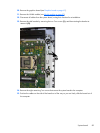
7. Remove the side panels (see
Side panels on page 92).
8. Remove the speakers (see
Speakers on page 78).
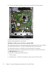
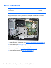
9. Remove the power button board (see
Power button board on page 94).
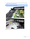
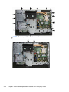
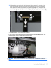
10. Remove the Torx screws that secure the bezel to the main system frame assembly, as follows:
●
18 total screws:
◦
Left: 5 screws
◦
Top: 5 screws
◦
Right 5 screws
◦
Bottom: 3 screw
Front bezel and display panel
97