


28 Chapter 2
Front and Rear Panel Features
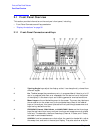
Front Panel Overview
frequency span are GHz, MHz, kHz, and Hz, whereas the units for reference
level are
+dBm, −dBm, mV, µV, and µA.
NOTE If an entry from the numeric keypad does not coincide with an allowed function
value (for example, that of a 12 MHz bandwidth), the analyzer
defaults to the nearest allowable value.
The Step Keys (
⇓ ⇑) increase or decrease the active function value. The step
size depends upon the current analyzer measurement. Each press results in
a single step change. For those parameters with fixed values (resolution
bandwidth), the next value in a sequence is selected each time a step key is
pressed. Step size is predictable (e.g., 10% of span for center frequency) and
can be set for some functions (i.e., center frequency). Out-of-range values or
out-of-sequence values will not occur using these keys.
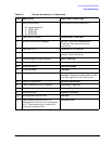
11 VOLUME. The VOLUME knob adjusts the volume of the internal speaker. The
speaker is turned on and off with the
Speaker On Off key in the Det/Demod menu.
12 EXT KEYBOARD. The EXT KEYBOARD connector is a 6-pin mini-DIN connector.
The keyboard can be used to enter screen titles and filenames.
NOTE To avoid damage to the analyzer, always turn off power before plugging a keyboard
into the analyzer.
13 PROBE POWER provides power for high-impedance ac probes or other
accessories. (+15 V,
−12.6 V, 150 mA maximum)
14 LO OUTPUT provides the proper local oscillator signal for use with external
mixers (Option AYZ).
15 IF INPUT connects to the IF OUTPUT of the external mixer (Option AYZ).
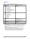
16 Return. The Return key accesses the previously selected menu. Continuing to
press
Return accesses earlier menus. Return also terminates entry of alpha
numeric functions (e.g., Title).
17 AMPTD REF OUT provides an amplitude reference signal of 50 MHz at –20 dBm.
Agilent ESA models E4402B, E4403B, E4404B, E4405B, E4407B, and E4408B
only.
18 Tab Keys are used to move around in the Limit editor, the Correction editor and
similar table-driven forms.
19 INPUT 50Ω (INPUT 75Ω for Option 1DP) is the signal input for the analyzer.
CAUTIONWhen operating in dc coupled mode on analyzers with Option UKB,
ensure protection of the input mixer by limiting the input level to
0 Vdc, +30 dBm.
When operating in ac coupled mode, ensure protection of the
input mixer by limiting the input level to 50 Vdc, +30 dBm.
20 The Next Window key can be used to select the active window in functions which
support split-screen display modes, such as Zone markers. (Refer to “Zone” in
the User’s guide for more information.) In such modes, pressing
Zoom switches