


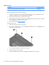
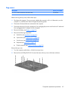
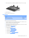
5.
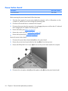
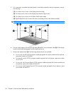
If it is necessary to replace the display bezel or the display assembly internal components, remove
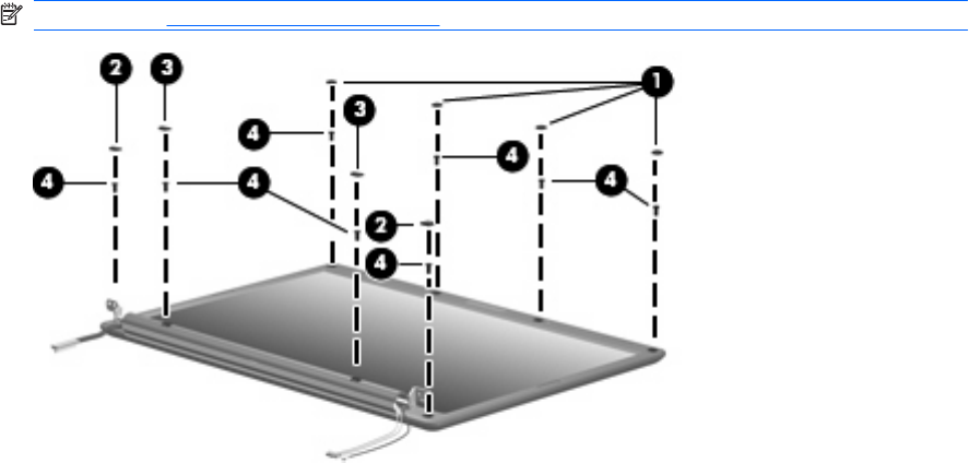
the following:
(1) Four rubber screw covers on the display bezel top edge
(2) Two Mylar screw covers on the display bezel bottom edge corners
(3) Two rubber screw covers on the display bezel bottom edge
(4) Eight Phillips PM2.5×8.0 screws that secure the display bezel to the display assembly
NOTE: See Camera module on page 38 for camera module removal information.
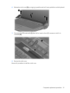
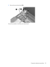
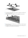
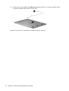
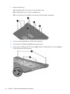
6. Flex the inside edges of the left and right sides (1) and the top and bottom sides (2) of the display
bezel until the bezel disengages from the display enclosure.
7. Remove the display bezel (3). The following display bezels are available:
●
For use only with HP G7000 computer models equipped with camera module and microphone,
spare part number 461868-001
●
For use only with HP G7000 computer models equipped with microphone, spare part number
461871-001
●
For use only with Compaq Presario F700 computer models equipped with camera module and
microphone, spare part number 461863-001
●
For use only with Compaq Presario F700 computer models equipped with microphone, spare
part number 461866-001
58 Chapter 4 Removal and replacement procedures