


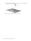
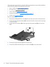
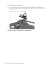
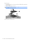
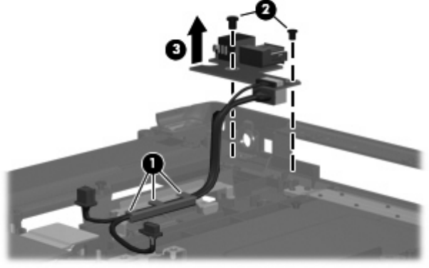
Remove the USB/power connector board:
1. Remove the USB/power connector board cable from the clips (1) built into the base enclosure
2. Remove the two Phillips PM2.5×5.0 screws (2) that secure the USB/power connector board to the
base enclosure.
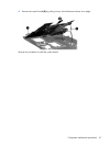
3. Remove the USB/power connector board (3).
Reverse this procedure to install the USB/power connector board.
70 Chapter 4 Removal and replacement procedures