


EL-MF877-00 Page 2
Template Revision A
refractory ceramic fibers
Components, parts and materials containing
radioactive substances
0
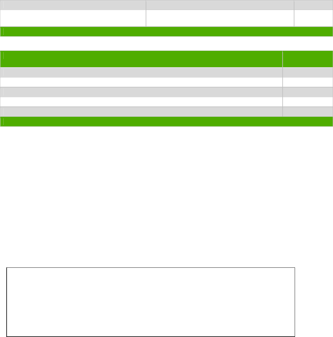
2.0 Tools Required
List the type and size of the tools that would typically be used to disassemble the product to a point where components
and materials requiring selective treatment can be removed.
Tool Description Tool Size (if
applicable)
Description #1: Bushing Screwdriver (HEX5.5MM)
Description #2: Crossing Screwdriver 2#
Description #3
Description #4
Description #5
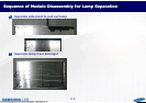
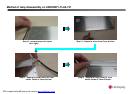
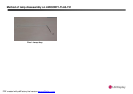
3.0 Product Disassembly Process
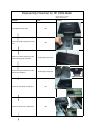
3.1 List the basic steps that should typically be followed to remove components and materials requiring selective treatment:
1. Lay the monitor on the desk, remove the VESA mounting cover with hand.
2. Unlock the 4 screws which they fix the VESA mounting by 2# screwdriver.
3. Unlock the 4 screws which they fix the stand by 2# screwdriver.
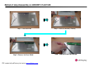
4. Remove the front bezel with hand from product
5. Remove the backcover with hand from Product.
6. Seprate the Keypad and backcover with hand
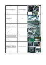
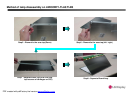
7. Unlock the 2 screws which they fix the chassis and panel, and then pull the LVDS out .
8. Unlock 2 screws for DVI port, D-SUB port, Power port, and 7 screws which they fix between chassis and PCA
boards, power board and IF board. Pull the wires out.
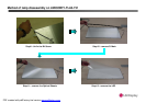
9. Unlock the 2 screws which they fix between the bottom-side and the base, and then unlock the 12 screws which they
fix between the base and base-cover.
10. Remove the arm-rear and then unlock the 4 screws which they fix between the arm-front and the rion.
11. To see the detail process are as attached files including assemble panel.
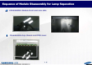
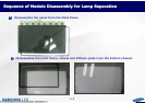
3.2 Optional Graphic. If the disassembly process is complex, insert a graphic illustration below to identify the items
contained in the product that require selective treatment (with descriptions and arrows identifying locations).