


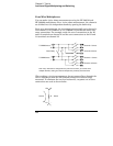
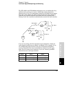
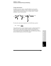
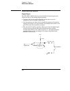
Using Attenuators
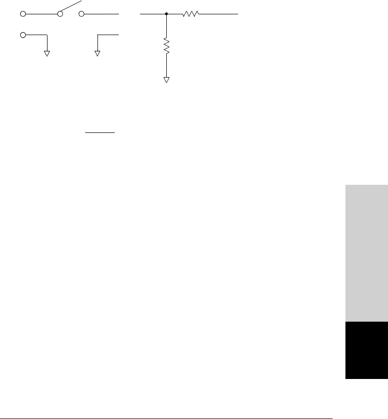
Provisions have been made on the HP 34903A circuit board for
installing simple attenuators or filter networks. An attenuator is
composed of two resistors that act as a voltage divider. A typical
attenuator circuit is shown below.
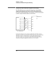
To select the attenuator components, use the following equation:
V
att
= V
signal
x
R
2
R
1
+ R
2
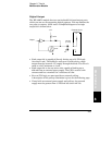
One typical use for the shunt component is with 4 to 20 mA transducers.
A 50
Ω, ±1%, 0.5 watt resistor can be installed in the R2 location.
The resultant voltage drop (transducer current through the resistor)
can be measured by the internal
DMM. Thus, the 50Ω resistor converts
the 4 to 20 mA current to a 0.2 to 1 volt signal.
R1
R2
HI
LO
V
signal
V
att
Module Reference
8
Chapter 8 Tutorial
Actuators and General-Purpose Switching
387