


Service Manual Removal and Replacement 2-1
2
Removal and Replacement
This chapter tells you how to remove and replace the notebook’s components and assemblies. The items
marked by • in the following table are user-replaceable.
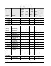
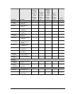
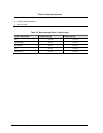
Table 2-1. Removal Cross-Reference
Assembly, display (page 2-23)
• Assembly, speaker (page 2-15)
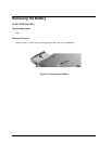
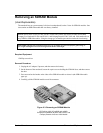
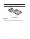
• Battery, main (page 2-4)
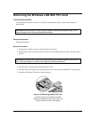
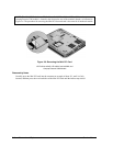
• Card, wireless LAN Mini PCI (page 2-7)
Case, bottom (page 2-59)
Case, top (page 2-26)
CPU module (page 2-44)
• Cover, keyboard (page 2-16)
• Door, Mini PCI (page 2-7)
• Door, SDRAM (page 2-5)
Doors, PCMCIA (page 2-60)
Drive, CD/DVD (page 2-20)
Drive, floppy (page 2-32)
• Drive, hard disk (page 2-9)
• Feet, rubber (page 2-12)
Heat sink (with fan) (page 2-40)
• Keyboard (page 2-16)
• Module, CPU (page 2-44)
Module, RJ11/1394 (page 2-48)
Module, SDRAM (page 2-5)
PCA, antennas (page 2-60)
PCA, audio (page 2-38)
PCA, I/R (page 2-36)
PCA, motherboard (page 2-50)
PCA, switchboard (page 2-19)
• Rubber screw plugs, display (page 2-12)
CAUTION: Always provide proper grounding when performing repairs. Without
proper grounding, an electrostatic discharge can damage the notebook and its
components.
NOTE: Reassembly steps are the reverse of the removal steps. Reassembly notes are included at the
end of each section below.
Symbols like these are displayed throughout this chapter to show approximate full-size
screw outlines. You can use these to verify the sizes of screws before you install them. Installing
a wrong-size screw can damage the notebook. (The symbol at the left represents an M2.5×4.0mm
T-head screw.)