


6.
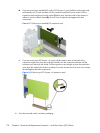
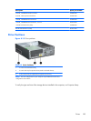
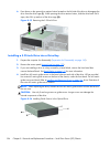
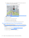
Press down on the green drive retainer button located on the left side of the drive to disengage the
drive from the drive cage (1). While pressing the drive retainer button, slide the drive back until it
stops, then lift it up and out of the drive cage (2).
Figure 8-15 Removing the 5.25-inch Drive
Installing a 5.25-inch Drive into a Drive Bay
1. Prepare the computer for disassembly (Preparation for Disassembly on page 169).
2. Remove the access panel (
Access Panel on page 170).
3. If you are installing a drive in a bay covered by a bezel blank, remove the front bezel then
remove the bezel blank. See
Bezel Blanks on page 172 for more information.
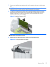
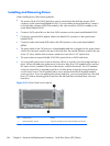
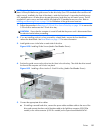
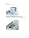
4. Install four M3 metric guide screws in the lower holes on each side of the drive. HP has provided
four extra M3 metric guide screws on the front of the chassis, under the front bezel. The M3 metric
guide screws are black. Refer to
Installing and Removing Drives on page 184 for an illustration of
the extra M3 metric guide screws location.
NOTE: When replacing the drive, transfer the four M3 metric guide screws from the old drive to
the new one.
CAUTION: Use only 5-mm long screws as guide screws. Longer screws can damage the
internal components of the drive.
Figure 8-16 Installing Guide Screws in the Optical Drive
186 Chapter 8 Removal and Replacement Procedures – Small Form Factor (SFF) Chassis