


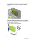
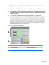

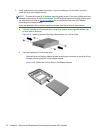
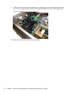
5. Install four M3 metric guide screws in the lower holes on each side of the drive. HP has provided
eight extra M3 metric guide screws on the front of the chassis, under the front bezel. The M3
metric guide screws are black. Refer to
Drives on page 68 for an illustration of the extra M3
metric guide screws location.
NOTE: When replacing the drive, transfer the four M3 metric guide screws from the old drive to
the new one.
CAUTION: Use only 5-mm long screws as guide screws. Longer screws can damage the
internal components of the drive.
Figure 6-17 Installing Guide Screws (Optical Drive Shown)
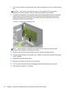
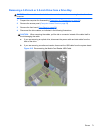
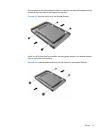
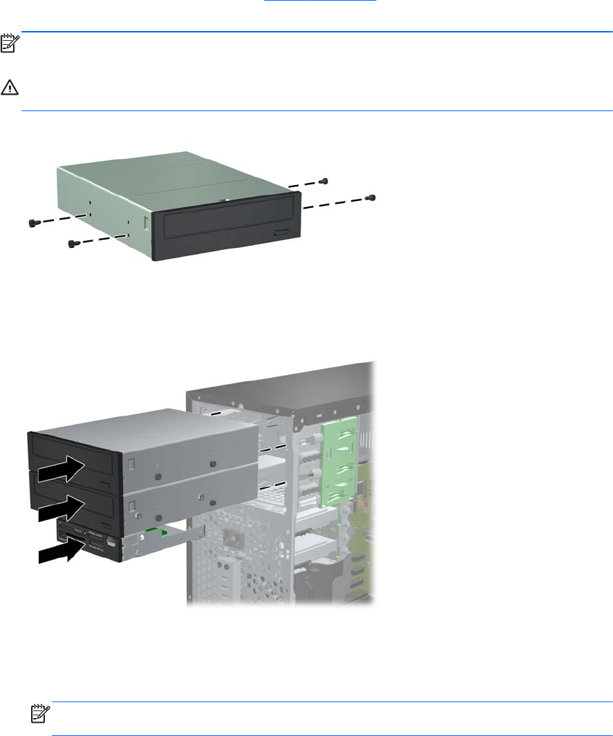
6. Slide the drive into the drive bay, making sure to align the guide screws with the guide slots, until
the drive snaps into place.
Figure 6-18 Sliding the Drives into the Drive Cage
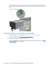
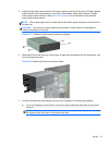
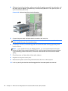
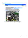
7. Connect the power and data cables to the drive as indicated in the following illustrations.
a. If you are installing an optical drive, connect the power cable and data cable to the back of
the drive.
NOTE: The power cable for the optical drives is a two-headed cable that is routed from
the system board to the rear of the optical drive bays.
Drives 73